This being the case i'm going to incorporate a sub enclosure into the part i wouldnt be able to reach easily.
the space available is 18"h x 15"d x 48"w
requirements
2.0pi flat to 20hz, i listen to alot of music wich requires cone control to 20 hz and output there.
.5pi output to 120 db, its in a van so i expect a 12db/octave boost below approx 100 hz due to transfer function.
id like to keep the amp small so around <250w would be great.
A tapped pipe or horn, NO PORTED OR SEALED WITH EQ PLEASE, BEEN THERE DONE THAT GOT THE T-SHIRT SOLD IT ON E-BAY, NO WIGGLE ROOM HERE. I have this room to use so I'm going to use it.
I want to order the driver from parts express so that's the only place to look, buyouts or whatever.
if you want i have hornresp and don't mind doing some tooling around if you want to drop a driver model your familiar with on me.
Driver budget up to $100 plus shipping.
ok, so i want to post an image of some noodling im doing, any assistance there appreciated
the image(s) must be hosted on the internet. does your ISP give you storage space or do you have a dropbox or similar online storage account
This is the box recommended in their PDF
An externally hosted image should be here but it was not working when we last tested it.
so ive been tooling around and id like approx a 4 m tapped pipe, flat to 20, low power requirements.
question, when modelling a non tapered pipe do i need to model each fold or can i assume just the s1/2 and s3/4?
specifically the bends, do i need to model the bends?
if so im guessing this is where akabak works wonders.
question, when modelling a non tapered pipe do i need to model each fold or can i assume just the s1/2 and s3/4?
specifically the bends, do i need to model the bends?
if so im guessing this is where akabak works wonders.
okay, now i know why this is fun!
i drew this pipe up on paper and started working dimensions out based on CSA and known path-lengths.
Thank god for the metric system!
ill post some screenies when i figure out how.
just found a suckout of major proportions(75db/oct) at the upper limit of bw.
i drew this pipe up on paper and started working dimensions out based on CSA and known path-lengths.
Thank god for the metric system!
ill post some screenies when i figure out how.
just found a suckout of major proportions(75db/oct) at the upper limit of bw.
it gave me an option to capture current data on the spl screen, where does it send the image?
Capturing the current results on the spl screen doesn't create an image, it captures the data so you can compare it later.
To capture an image of the current screen, make sure the Hornresp window is active, press alt and print screen. That captures the image of the active window to the clipboard. From there you can open MS Paint (or similar), paste the image into that program and save the image. (Crop it to the correct size if necessary before saving.)
Then you need to host the pic somewhere. You can upload it directly to your diyaudio post or you can use an external site like Photobucket or tinypic. If you host externally you need to copy the image url and post it in the diyaudio post where you want the pic to appear.
Very simple after you've practiced a few times.

this may work better.
since im not picky perhaps i could just lay it out on my wood and slap it together, the pipe produced output to 20hz and will do so loud enough for a first effort.
perhaps ill hear something i like enough to tweak it.
is that a rabbit hole i see?
since im not picky perhaps i could just lay it out on my wood and slap it together, the pipe produced output to 20hz and will do so loud enough for a first effort.
perhaps ill hear something i like enough to tweak it.
is that a rabbit hole i see?
Attachments
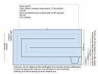
is that a rabbit hole i see?
I don't know what you see, but according to post #1 this won't fit in the available space.
the space available is 18"h x 15"d x 48"w
The picture as shown will be 34.5 x 12.5 x 48. (Since the 48 inch length is fixed it might change the sim but I didn't take the time to investigate that for reasons that will become clearer in a minute - atm I think your last concern should be properly laying out the fold and accounting for bends.)
The second problem is that (as shown) the 34.5 inch height does not account for 5x board thickness at .75 inch, so either the csa would have to change or you would have to make it 35.25 inches high to keep your 558 cm2 csa.
Usually people share the details of the Hornresp sim first before trying to fold it up to make sure it's a good design before going full steam ahead. Have you checked to see if this design offers any benefit over a ported box yet?
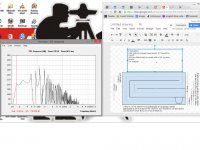
Here's a quick sim.
An externally hosted image should be here but it was not working when we last tested it.
My TH sim doesn't look like yours. The light grey line in the spl chart is a ported box with 46 liters volume (I just copied the design in post 10 and lengthened the port to hit 20 hz tuning), the dark black line is your design with 266.5 liters. Your design looks wildly spiky, it isn't usable above 55 hz, and doesn't offer much extra spl despite being almost 6x larger. The displacement graph shows your design is tuned considerably lower than 20 hz. Both designs shown at xmax (actually near xmax, I didn't want to spend too much time aligning them exactly), the ported box took 40 volts to get there, the tapped horn only needed 27.1.
Overall I would not be happy with this, I would not build it.
Last edited:
Ya good eye there, the van i'm going to put this in is different from the original post.
I see your point about extra output, all the in band output is pretty close to the vented sim.
I'm going to tool around with the sim some more to see if i cant flatten it out.
As far as getting the spikes out, i wanted to try a simple building line first just to see how it sounds.
I may also build the vented box and compare them so i have a frame of reference.
I did not notice the difference in height, ill keep the 200mm inside height and adjust the dims.
thx for input.
Last edited:
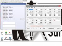
perhaps this is it?
Sorry bout all the extra crap on the screenies.
If you don't want the extra stuff press alt, not ctrl.
- Status
- This old topic is closed. If you want to reopen this topic, contact a moderator using the "Report Post" button.
- Home
- Loudspeakers
- Subwoofers
- okay im going to build a rack in my van for work...