Which NTC to be used for the 0.4F cap with 2KVA transformer with constant current of 5 amps of current.
Want to build a 100W Class A amplifier so considering these specs:
I have a class A audio amplifier requirement where the Capacitor bank is about 0.4Farad in total for both the rails in the secondary. 1.2KVA transformer. Constant current consumption will be about 3 to 4 Amperes Can you please recommend the right NTC for the inrush current limiting.
you need two current limitiers.
The primary start up current to get the transformer working needs an added resistance in the primary circuit that gets shorted by a time delayed relay after about 200ms. What mains voltage are you using?
The secondary current builds rapidly after the transformer has started to charge the discharged capacitors.
This is exactly the duty that NTCs are used for and is detailed in the NTC datasheets.
This added resistance in the secondary circuit is best shorted out with a time delayed relay set to about 10s.
you need two current limitiers.
The primary start up current to get the transformer working needs an added resistance in the primary circuit that gets shorted by a time delayed relay after about 200ms. What mains voltage are you using?
The secondary current builds rapidly after the transformer has started to charge the discharged capacitors.
This is exactly the duty that NTCs are used for and is detailed in the NTC datasheets.
This added resistance in the secondary circuit is best shorted out with a time delayed relay set to about 10s.
Mains voltage:
For AB about 70 to 80V.
For 100Wclass A about 50V
working on a BA2000 class H as well so there it might be about 70V for one rail and 140 for another one.
but mostly a generic approach.
Regarding the transformers it would be about 2KVA in general so there will be an NTC in starting of the softstart ckt.
so the value of the cap is quite large so it would be in big Joules value. so do we need to use a an NTC with larger Joules value.
consider Ametherm NTC so acc to their site for 50V peak and 0.4F the total energy is about 500Joules so we need to take an NTC for 500Joules.
http://www.ametherm.com/inrush-current/
If you look at the bottom of the page
http://www.ametherm.com/inrush-current/megasurge-inrush-current-limiters.html
you will find the Megasurge NTC with more than 500Joules capability but which one to pickup like take about an NTC with 750 joules would be sufficient?
Last edited:
Take this as an example NTC
Ametherm MS35 3R030 ---3 ohm / 30 Amp Inrush Current Limiter Data Sheet
what is that parameter mean?
Max Capacitance @ 120 VAC: 51600 µF
Max Capacitance @ 240 VAC: 13024 µF
Max Capacitance @ 480 VAC: 3010 µF
Max Capacitance @ 680 VAC: 1500 µF
so where does this capacitor comes in the circuit?
Ametherm MS35 3R030 ---3 ohm / 30 Amp Inrush Current Limiter Data Sheet
what is that parameter mean?
Max Capacitance @ 120 VAC: 51600 µF
Max Capacitance @ 240 VAC: 13024 µF
Max Capacitance @ 480 VAC: 3010 µF
Max Capacitance @ 680 VAC: 1500 µF
so where does this capacitor comes in the circuit?
The NTC design info relates to a direct mains VAC rectifier charging a capacitor. Calculate 0.5 x C x V x V for each of those examples and they give the same Joule rating that will not hurt the NTC during a mains turn-on.
You need to determine the Joule requirement of your DC cap - and then find a somewhat larger NTC.
The following link has some NTC advise that may help a bit:
http://dalmura.com.au/projects/Valve%20amp%20fusing.pdf
You need to determine the Joule requirement of your DC cap - and then find a somewhat larger NTC.
The following link has some NTC advise that may help a bit:
http://dalmura.com.au/projects/Valve%20amp%20fusing.pdf
A GE CL-30 can charge 6,000uF with rectified 120VAC supply (ie. to 170VDC), so can cope with 87J of energy throughput.
NTC should only be connected in series, so 6 of those CL-30 would need to be placed in series on the secondary side to alleviate turn-on surge current.
You then need to determine what the max continuous rms current through the NTC devices would be, and relate that to a possibly derated 8Arms capability.
If you wanted, the NTC could be placed on the primary side to also manage the transformer in-rush. The energy throughput requirement then goes up - but probably not by a substantial level. Placing the thermistor on the primary has the advantage that the max continuous current may be lower.
There may be other NTC devices that have similar energy capability but with a lower resistance, if series resistance is aesthetically displeasing to you, but that does trade-off the level of in-rush.
And of course you could contemplate adding complexity and bypass the thermistor string, but they are designed for this activity so the KISS principal is worth considering.
you need two current limitiers.
The primary start up current to get the transformer working needs an added resistance in the primary circuit that gets shorted by a time delayed relay after about 200ms. What mains voltage are you using?
The secondary current builds rapidly after the transformer has started to charge the discharged capacitors.
This is exactly the duty that NTCs are used for and is detailed in the NTC datasheets.
This added resistance in the secondary circuit is best shorted out with a time delayed relay set to about 10s.
so one comes in primary and once comes in secondary.
So instead of having a 5 ohm resistor in the primary and short after 200ms can we use an NTC there too.
Actually what Im thinking to use is use a NTC right after the EMI filter and then use another NTC in series with the primary of the trafo and short after 0.5sec and then use another NTC in the secondary of the transformer before the Large caps and then short after 10 secs. Is that fine?
Can you clarify why you need a 2kVA transformer, when your DC load appears to be constant and about 2x 50V x 5A = 500W ?
Can you clarify why you would think that inserting an NTC in the mains primary-side circuit at one location, and then another NTC in the mains primary-side circuit at another location, and then another NTC in the secondary side circuit, is of any more benefit than just a single NTC in the mains supply ?
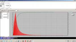
If you do a PSUD2 simulation of your intended DC power supply you will be able to estimate the reflected primary side peak current due to the cap charging. You can then compare that peak current with the likely peak current from just the in-rush of a 2kVA transformer - that will indicate how influential the cap charging is compared to the in-rush. To get a reasonable simulation outcome you would need to have carefully measured the transformer primary and secondary winding resistances (as they will no doubt be quite low in value).
Can you clarify why you would think that inserting an NTC in the mains primary-side circuit at one location, and then another NTC in the mains primary-side circuit at another location, and then another NTC in the secondary side circuit, is of any more benefit than just a single NTC in the mains supply ?
If you do a PSUD2 simulation of your intended DC power supply you will be able to estimate the reflected primary side peak current due to the cap charging. You can then compare that peak current with the likely peak current from just the in-rush of a 2kVA transformer - that will indicate how influential the cap charging is compared to the in-rush. To get a reasonable simulation outcome you would need to have carefully measured the transformer primary and secondary winding resistances (as they will no doubt be quite low in value).
Last edited:
but since the NTC is on the secondary with relay shorting after 10sec so wouldnt there be a pop from the speaker once the relays are turned on as one for positive and another for negative.NTCs are good. Use them.
Select the correct resistance value to give effective current limiting.
How about having a Megasurge NTC may be few in parallel in the primary itself and then short after 10secs. Just one NTC and one relay. It would do the job of both trafo inrush and caps inrush.try it, listen to what you can hear and measure the effect.
A 600J MS35 5R025 may be sufficient for your turn-on.
You can estimate the 'hot' resistance of the NTC, and add that to your transformer effective supply resistance within PSUD2 to indicate what affect if any it would have.
You would need to use something like PSUD2 to identify the likely diode peak current, and check that against your chosen diode datasheet.
You should also justify to yourself why you need 400,000uF - that is a large energy hazard. Are you powering more than one amplifier module? If so, then you would get better inter-channel isolation by splitting the capacitance up so that amplifier current only flows through its associated power supply capacitance. Splitting would also reduce diode noise, as a lower current rated diode could be used and wiring would have lower current and dI/dt.
An NTC in the primary circuit is not an effective current limiter for the secondary side current into discharged capacitors.
The NTC manufacturers all show the capacitor current limiting NTC in the capacitor circuit, not on the other side of a transformer.
Andrew, I can't see how that logic works - the transformer is just a series impedance between the AC mains and the secondary side (eg. for an isolation transformer), and if the turns ratio is not unity then there is effectively a current ratio. There is no magic black-box inside the transformer. If anything, the Joule throughput of a mains side NTC is a titch more when passing capacitor charging energy through a transformer due to transformer losses on the way.
The manufacturer data is related to the typical application of a switchmode power supply with mains side rectification.
Last edited:
Direct to mains SMPS is but one application. There are many capacitor charging applications where some form of NTC current limiting is useful. Many of these other typical uses can be after a mains transformer. Yet the NTC manufacturer show the NTC in the capacitor circuit, not on the other side of the transformer.
The transformer is a voltage ratio device. It is very effective at that. emf-in:emf-out is strictly defined by the turns ratio.
Current does not follow that ratio.
Current is emf-out/impedance of the output circuit, where the primary side impedance is only a small proportion of the total secondary circuit impedance.
Andrew, perhaps a thought experiment is in order.
If an ideal transformer was placed between a primary side NTC and a secondary side rectifier/capacitor, then I'd suggest the NTC experiences the same energy throughput as the transformer turns ratio is changed to align with the datasheet levels for different VAC and the rated rectifier/capacitor.
Post #5 shows a set of ratings. One could have a 120VAC supply, and a 120:240 ideal transformer and 13024 µF on the secondary side, and the NTC would think it was feeding 120VAC to a 51600 µF cap. Similarly for a 240VAC supply, and a 240:120 ideal transformer and 51600 µF cap on the secondary side, and the NTC would think it was feeding 240VAC to a 13024 µF. Similarly for any other combination, including a 1:1 isolation transformer.
The commonality is that the throughput energy experienced by the NTC is the same level of joules.
It doesn't matter if the NTC is on the primary or secondary side, it experiences the same level of energy throughput needed by a secondary side capacitor charging up. As such, an NTC in a primary circuit can be just as effective as an NTC in a secondary side.
In order to appreciate how influential the cold resistance of an NTC is when the NTC is on the primary side or the secondary side of a transformer, then I suggest checking out PSUD2 and the 'source impedance calculator' and its help info and seeing how primary side resistance relates to secondary side resistance.
- Status
- This old topic is closed. If you want to reopen this topic, contact a moderator using the "Report Post" button.
- Home
- Amplifiers
- Power Supplies
- NTC recommendation for 0.4F cap 51V transformer