New guy with Port location question
Hi diy world, how is everyone doing.
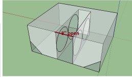
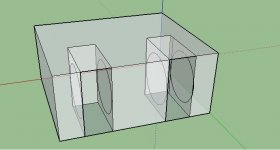
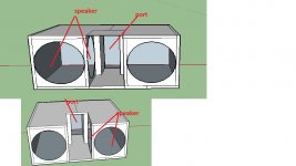
I am building a ported box with 4 alpine sws 12d4 drivers and request some help with the port location and calculation.
Thanks
Please be advised my speaker design knowledge is poor and I am will to learn.
I bring nothing to the table but questions and willingness to learn. I know how to use bassboxpro but not hornresp.
I welcome any help and experience.
Last edited:
Hi diy world, how is everyone doing.
Very well thank you
And the question is
OK. Hopefully someone who knows a lot more about speaker design than do I will be able to help out.
Cool
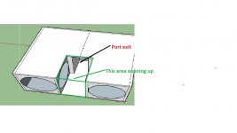
Yes, but to a lesser degree. There is also the problem that the excursion of the inner speakers will modulate the port size.What if the panel area that are outline with green are removed would that still affect the port tuning.
A better way to reduce frontal area with multiple speakers is a slot arrangement, which can be done either with the speakers facing each other (push push) or cone to magnet (push pull) with the reversed driver polarity reversed. Triangular ports can be but in 2 or four corners of the cabinet.
Push pull mounting reduces even order distortion, but sacrifices a bit more cabinet volume to the plenum (slot).
This post will give you a better idea of the arrangement:
http://www.diyaudio.com/forums/subwoofers/255010-compact-2x15-ppsl-using-dayton-pa385-8-drivers.html
A better way to reduce frontal area with multiple speakers is a slot arrangement, which can be done either with the speakers facing each other (push push)
How would I go about calculating the slot size for the drivers using bassbox pro
Last edited:
The slot size does not need calculation, other than reducing it's volume from the box size. Practically speaking, the depth of the driver plus the depth of the mounting ring determine the minimum slot width if front mounting.How would I go about calculating the slot size for the drivers using bassbox pro
Rear mounting the speakers in a push-push arrangement the slot width could be reduced to around 2 inches (50mm).
Port volume and the volume the drivers physically occupy also must be reduced from the gross volume to figure the net box volume.
The slot size does not need calculation, other than reducing it's volume from the box size. Practically speaking, the depth of the driver plus the depth of the mounting ring determine the minimum slot width if front mounting.
Rear mounting the speakers in a push-push arrangement the slot width could be reduced to around 2 inches (50mm).
Port volume and the volume the drivers physically occupy also must be reduced from the gross volume to figure the net box volume.
Is this close to what a push push layout look like.

Yes, as drawn it could be loaded push push or push pull. Rather than going two cones deep, build two slots side by side each with two drivers, and separate the two cabinet portions with a center wall for more even cone pressure, and a less pronounced pipe resonance peak/dip.Is this close to what a push push layout look like.
View attachment 539419
Alternating the ports top and bottom will make for better heat transfer through the cabinet, as the cooler air will enter the bottom, and as the air is heated will rise out the upper ports.
The whole idea cannot work. Four speakers in a BR typically require so much volume, that mounting them on a side is never a problem.
Why use 4 drivers? This only makes sense in a closed enclosure with the proportions as sketched. And then slam them with all the power they can handle to push through the inherent low frequency roll off.
Why use 4 drivers? This only makes sense in a closed enclosure with the proportions as sketched. And then slam them with all the power they can handle to push through the inherent low frequency roll off.
Yes, as drawn it could be loaded push push or push pull. Rather than going two cones deep, build two slots side by side each with two drivers, and separate the two cabinet portions with a center wall for more even cone pressure, and a less pronounced pipe resonance peak/dip.
Alternating the ports top and bottom will make for better heat transfer through the cabinet, as the cooler air will enter the bottom, and as the air is heated will rise out the upper ports.
Am I getting close

As an alternative to this you could make the baffle face M (or W) shaped instead of having straight slots. This may (or may not) waste less cab space depending on how wide the baffle is. It will also raise the slot port resonance in frequency.
Something like this or variations on this with different angles. Even if you just do narrow slots like you showed but make them V shaped, that can save space and push resonances up. You just have to make sure the drivers will fit without getting in each other's way and have access panels for mounting to the rear of the baffle board if necessary before cutting wood.
An externally hosted image should be here but it was not working when we last tested it.
Kiki, make some calculations first, and you will understand the wisdom of my earlier remark. You are not barking against the wrong tree, there is no tree. Only in a closed enclosure would it make sense to put that many drivers in such a relatively small volume.
This site mh-audio.nl has all the calculators you need. Just punch in the T/S parameters and see how large an enclosure needs to be with even one of the drivers you are planning to use. You will be surprised.
This site mh-audio.nl has all the calculators you need. Just punch in the T/S parameters and see how large an enclosure needs to be with even one of the drivers you are planning to use. You will be surprised.
- Status
- This old topic is closed. If you want to reopen this topic, contact a moderator using the "Report Post" button.
- Home
- Loudspeakers
- Subwoofers
- New guy with port question

