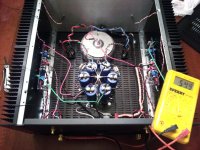
So Iam about to start up one channel of my F5, I am double checking everything and the speaker positive binding post is connected to ground when tested w/my meter. This is not good, right? I disconnect everything...the binding post and RCA's are isolated from chassis. The mosfets are not shorting on the heatsinks. When I disconnect the chassis ground the connection between the positive speaker out and ground (or black binding post) goes away.
Is this just the way F5's are? Is there some sort of circuit design that Positive speaker out has continuity with ground? Do I have an issue?
Power supply is fine...25ish volts. Scared to hook up the boards now...
HELP!
Is this just the way F5's are? Is there some sort of circuit design that Positive speaker out has continuity with ground? Do I have an issue?
Power supply is fine...25ish volts. Scared to hook up the boards now...
HELP!
Attachments
both channels do the SAME thing?? Or only one??
When you say continuity, are you saying virtually Zero ohms or some other value??
Also, the ground connections on your PS caps should ALL be at the center, none off to the side...
_-_-
PS. troubleshoot one channel at a time - disconnect the PS to one channel and the ground.
do ohms across the mosfets too... you are looking for the same reading you have found earlier. Also
the mosfets to the ground of the PS or board.
Be sure the PS has zero volts on it. unplugged, and probably with a resistor hung between the rails
and ground to drain it all the way down... then remove the resistor(s) to test this stuff...
...sounds like a miswiring.
PPS. reverse the ohmeter's leads for the test where you have found the problem, if the reading is *different*
then you are seeing a diode somewhere, which may be a semiconductor junction - or similar.
Last edited:
Both channels, same thing.
There is about 60ohms resistance. I reversed the DMM leads and the rsitance changes, but not by much.
When I disconnect the chassis ground there is no continuity between the black speaker out and chassis. So the issue must be in the boards/PSU.
Bear: You say the ground connection of the PS caps should all be at center...I think they are. The center ground (bolt in that center of "star") is where my PCB board ground and chassis ground go to. One bank of caps is - the other is + to this connection. Again, the PSU measures 25ish volts + and -.
I'll post better pics soon. Thanks.
Thought I saw a wire going to a ground lug on one of the caps, but hard to see in the pix.
Ok, so if you disconnect the *chassis ground* there is no continuity with the output + and ground.
What is insulating the output + connector??
Will this still happen if you remove the wire from the connector or at the board and check it there??
The BLACK side is usually GROUND.
Do you have a wire back to the PS ground from the Black side?
The RED side is usually +.
If the black side shows continuity to ground, it should!!
In fact it might be closer to zero, unless you have a resistor connecting the chassis to PS ground.
If this is all that is happening then it is ok fine.
Otherwise there is no path that should provide a low resistance that goes through the chassis...
What is the resistance between the PS ground and the ground speaker post?
What is the resistance between the PS ground and the chassis??
Now there is a feedback network between the output and input, it is a pair of 100ohm resistors in parallel, then a 10 ohm to ground at the jfets... two of these, so about 30 ohms to ground. That would be normal, IF this is what you are reading. R's: 1,2,5,6,7,8
See attached schematic.
Attachments
Last edited:
Thanks for all the help guys.
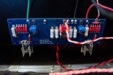
I've got 53.5 ohms between the black and red binding posts. The following conditions are the same across both channels.
If I disconnect the chassis ground there is no change, 53.5 between black and red biding posts. If I disconnect the chassis ground there is no continuity between binding post and chassis. This proves the biniding post/mosfets are isolated.
If I disconnect the PSU and chassis ground from boards I still get 53.5 ohms between black and red binding posts. This proves it's in the boards.
I double checked the N+P transistors and they look correctly oriented, pin-out wise.
I've got 47 ohms between V+ in pad on board and ground. 37 ohms between V- in pad and ground.
On second thought this may be normal? This is my first non-chip amp build and I am paranoid about everything. Perhaps this is the way it should be.
Here are some better pics...
Thanks again for all your help. I really do appreciate it.
Attachments
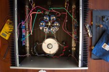
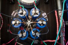
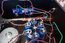
You have the bridges going to the cap's ground lug. They should both go to the star's center, not to the caps. The suggestion to put yr grounds all to the star center usually results in lower hum and noise at the output...
...you can put a tab up in the air and solder to that off the center star, if that will help make the connections.
sounds like ur amp is fine.
I am worried however about how you are grounding the chassis... should be back to the star point...
Fire that puppy up!! (you can fire up one channel at a time too...)
_-_-
You have the bridges going to the cap's ground lug. They should both go to the star's center, not to the caps. The suggestion to put yr grounds all to the star center usually results in lower hum and noise at the output...
...you can put a tab up in the air and solder to that off the center star, if that will help make the connections.
sounds like ur amp is fine.
I am worried however about how you are grounding the chassis... should be back to the star point...
Fire that puppy up!! (you can fire up one channel at a time too...)
_-_-
Bear: I hear ya on the bridges going to the center ground. Good idea. The chassis is grounded to the center star via NTC.
Still scared to fire it up. May work up the courage tonight.
Amp is up in running, full bias (.59v) both channels.
SOUNDS GREAT.
I was running was passive preamp (25K) pot into the amp with a tube buffer between the pot and amp. Interesting thing is, it sounds way better without the buffer. Guess it doesnt need the impedence matching and the caps/tubes in the buffer just suck SQ. Exact opposite effect the buffer had on my tripath amp.
SQ is great. Bass isn't quite as pronounced as with my tripath amp. It seems to have a little more punch.
The F5 is dead quiet. Highs are more extended and smoother the the tripath. Soundstage is comparable in size but with better placement. The tripath feels "congested" compared to the F5 but the tripath amp has more low/midrange drive I think. But the F5 is not broken in yet. So far I like what I am hearing.
Thanks again guys. Couldn't have done it without you.
SQ is great. Bass isn't quite as pronounced as with my tripath amp. It seems to have a little more punch
Don't mistake accuracy for light bass. I sometimes think the bass as lacking, but it because its not over emphasized. With the right speakers bass is very good.
Glad its working for you.
Actually, it was phase inverted. I had the speakers cables at terminated at the speakers inverted because my last amp was inverted. After changing the cables back to non-inverted it may be picked up some more bass density. Or it just might be me. I've heard the tripath/class D bass described as "cyborg bass". That may be right. I can hear actual notes with the F5, not just feel them.
Another observation:
Typically I am a vinyl guy but this thing loves CD's. I am running a passive 25K pot in front of the F5 and I have enough volume (feedback resistors are 200ohm/+6db gain). But The CD player pushes the amp harder than my phono stage. I know for a fact my vinyl rig is a better sounding set up than my CD rig. I am guessing the F5 likes the extra input voltage the CD player is providing vs my phono rig. Which only means one thing...
I might have to build a preamp. Jfet BOZ? Any recommendations?
- Status
- This old topic is closed. If you want to reopen this topic, contact a moderator using the "Report Post" button.
- Home
- Amplifiers
- Pass Labs
- New F5 build: Speaker positive showing continuity w/ground