I've got an old Cary amp that I want to refurbish and update with new components that would improve the sound. I think modern high-quality caps such as Jensen or Auricap might help.
I cannot read a schematic, so I really need someone to take a look at the schematic I've attached and tell me what components are in the signal path that a simple solderer like me could replace to improve the sound.
Any other advice would be appreciated, too.
Best wishes,
earplay
I cannot read a schematic, so I really need someone to take a look at the schematic I've attached and tell me what components are in the signal path that a simple solderer like me could replace to improve the sound.
Any other advice would be appreciated, too.
Best wishes,
earplay
Attachments
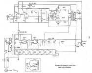
Well, the quick answer to your question is the two .22 ufd capacitors feeding the 807s. These are directly in the signal path.
Nice polypropylene caps here should help. Some will recommend paper and oil which are slower, but with an output transformer to go through the faster dielectric is usually prefered. (better HF response) But it really depends on what you hear and prefer. The 33 ufd cathode bypass cap could be a little larger in value too.
Actually, I would have named this amplifier the cheap and dirty 807. A power supply with no filter choke that relies only on a huge input capacitor that the rectifier tubes really don't like. And the one 6SL7 serving as a paraphase style invereter IMHO is one of the worst phase inversion circuits there is.
BTW, the schematic has an omission. The negative side of the power supply capacitors are not connected to ground return. And the filament winding has a grounded center tap as well as two resistors in a simulated center to ground. What's that all about? (Unless the CT is not really on center.)
Victor
I'm with Victor. Giant caps must have been a cheaper than filter chokes. Sad to see a company like Cary doing this. Running the stock power supply through PSUD, I read ~1.3 V ripple - not great.
Assuming you'd want to keep the twin GZ37s, try the following:
I get ~0.17 V ripple - much nicer. It does suppose you've got room for the filter choke in (or on) the chassis. If you decide to go this route be sure the 4 uF caps are rated at 350V or higher. The 220k resistors should be 2W.
Curious that Cary felt the need to use twin rectifiers in this application. A single 5U4GB would've done just fine (minus the ginormous cap of course). 5U4GB + 2uF + 7H + 470uF = ~0.15V ripple.
Assuming you'd want to keep the twin GZ37s, try the following:
An externally hosted image should be here but it was not working when we last tested it.
I get ~0.17 V ripple - much nicer. It does suppose you've got room for the filter choke in (or on) the chassis. If you decide to go this route be sure the 4 uF caps are rated at 350V or higher. The 220k resistors should be 2W.
Curious that Cary felt the need to use twin rectifiers in this application. A single 5U4GB would've done just fine (minus the ginormous cap of course). 5U4GB + 2uF + 7H + 470uF = ~0.15V ripple.
- Status
- This old topic is closed. If you want to reopen this topic, contact a moderator using the "Report Post" button.