Hi guys, I'm putting together a mono subwoofer amp using pre-fabricated power amp and preamp modules and need to find a suitable way to get +/-15v to power the opamps in the crossover/preamp circuit, there are only a few opamps so doesn't need to supply very much current.
The main amp will be running off +/-56V, so would like to find a quick and easy way to reduce this to provide power for the opamps.
I was thinking of maybe just using a couple of dropping resistors and zener diodes, if this would work then what value resistors should be used?
Another option I thought of was using dropping resistors with 7815&7915 voltage regulators.
I have seen more complicated designs using bjt's with zener diodes on the base and a bunch of extra components, which while I'm sure would be better and more stable, it is adding more complexity which I am trying to avoid.
I'm not concerned about what would perform best etc, I just need the simplest way to make it work. It's just an old sub only going to be used for parties etc.
Any ideas or advice would be appreciated.
how much opamps exactly, or better, how much current are they drawing?
Dropping resistor and 7815/7915...hmm.. will only work if you can be sure opamps are always pulling current, otherwise no drop and "poof" do the 7815/7915.
Maybe a simple shunt, with some 820R/5W resistors and 15V zener? That would provide about 50mA for the opamps, but burn some 2W in the 820R resistor.
Seen this in a circuit design, but use four 25v 220uf capacitors in series and then just tap of one of the capasitors to give you 14V. or use 3 caps and tap of one of them, then use a resistor to drop the voltage. You should be able to get -14V by tapping of another cap and using the middle connection of the two caps a a ground point.
I've added an image, otherwise you could use resisters or transistors.
I've added an image, otherwise you could use resisters or transistors.
Attachments
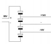
I believe the caps are common DC caps used in dc circuits as they could only be used in one direction. So basically the caps are used as a string of batteries and then just tap of them. The current or power should travel through the caps. As you are wanting to power a op amp it shouldest use much current otherwise the caps would warm up if current was dragged through them.
A series Zener would reduce your voltage.
Then add on a shunting Zener in parallel with some smoothing, noise reducing electrolytic.
56Vdc down to 15Vdc:
Three 10V 500mW Zeners knock off 30V and get one down to 26Vdc and be able to pass anywhere from 0.1mA to 49mA.
Add in a 1k, or 1.5k, resistor to knock off a further 11V.
Any excess that the opamp does not use in passing the resistor gets shunted through the final Zener. Aim to pass ~25% to 50% of the maximum current of this Zener through here. 15V 500mW has a maximum rating of 33mA, therefore pass 8mA to 16mA
500mW Zeners are very cheap and don't mind running at near maximum power rating.
You could build this as a 2 stage filter.
Series Zener followed by shunt cap, then series resistor followed by shunt cap.
This will get the main PSU ripple down very low by the time it arrives at the opamp/s and be substantially impervious to mains voltage variation and impervious to main supply rail variation.
Last edited:
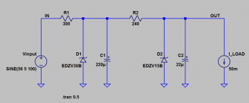
You can get another 30dB (32X) of ripple attenuation if you use two zeners and two resistors for V+ (plus 220uF capacitor), and another two zeners and two resistors for V- (plus 220uF capacitor). It all depends on how ugly you think your +/- 56V supplies are, and how pristine you want your +/- 15V supplies to be.
_
_
Attachments
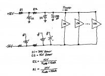
Or you could take R1, multiply by 10x before D1 and omit the rest; use the same 220uF across D1, and add an emitter-follower (collector to Vin, base to D1 anode, emitter to Iload) and so get (R1/hfe) lower impedance supply, and a prime filter frequency a decade lower (= 20dB over a single-stage R/zener) with very 'flat' supply impedance thereafter - but not as ultimately brutal at HF as Mark's suggestion.
Everything is a matter of picking compromises!
Everything is a matter of picking compromises!
Last edited:
A sensible proposition, at last: dropping voltage with series zeners or similar techniques is generally a lousy idea because it magnifies the instability proportion, and zener droppers tend to change into short-circuit droppers at the first start on a capacitive load.Or you could take R1, multiply by 10x before D1 and omit the rest; use the same 220uF across D1, and add an emitter-follower (collector to Vin, base to D1 anode, emitter to Iload) and so get (R1/hfe) lower impedance supply, and a prime filter frequency a decade lower (= 20dB over a single-stage R/zener) with very 'flat' supply impedance thereafter - but not as ultimately brutal at HF as Mark's suggestion.
Everything is a matter of picking compromises!
Opamps are not too picky, and safety + efficiency is probably a more sensible goal than ultimate supply rejection.
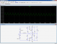
A buffered zener provides good enough regulation and ripple rejection, and can survive mishaps with suitably located resistors and suitably absent capacitors at critical places.
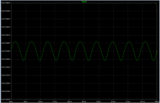
This example can be adapted to suit most low power situations: it provides up to 150mA with an Iq of 5mA, and the residual ripple remains low enough, even in the presence of 10Vpp at the input
Attachments
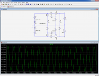
... the residual ripple remains low enough, even in the presence of 10Vpp at the input
Post #11 waveform appears to have 2 millivolts peak-to-peak ripple.
If member flyingtele desires even less, the two zener schematic below gives 0.1 millivolts peak-to-peak ripple with the same 10Vpp input. At the cost of less efficiency / greater quiescent current.
_
Attachments
an approach I see in many commercial audio amps. jellybean parts means less cost / purchasing problems.using dropping resistors with 7815&7915 voltage regulators.
- Status
- This old topic is closed. If you want to reopen this topic, contact a moderator using the "Report Post" button.
- Home
- Amplifiers
- Power Supplies
- Need a +/-56V to +/-15V voltage reducer for opamps