This is a schematic of a high resistance bridge at NIST. The guard circuit has nominal rx in the neighborhood of Rx.

An extreme example of guarding, but not very relevant to my situation.
I managed to instal the two guard conductors under the BSP92, and I used a fresh one, because the previous one had been soldered, unsoldered, resoldered, manipulated, and it might have been contaminated.
The result was meagre: a few pA. Now, I still miss about 40pA.
Interestingly, the current looks stable: heating the circuit gently and uniformly with a heat gun doesn't affect it. This raises the possibility, in case all the rest fails, to use a "blind fix", like reducing the 900M resistor, but I am not comfortable with this type of solution: the unknown cause might evolve with time, unpredictably and perhaps violently.
I would very much prefer to understand the root cause and address it properly, but at the moment, I have explored all the possibilities I could think of
Have you taken into account that the input bias current of the TLC272 and input offset current can each be as much as 60pA?
If you place the op amp into buffer mode and just connect the other input to ground with a 1G or 10G resistor you should be able to measure the input bias current you measuring the output voltage and the input bias current is Vout/R
If you place the op amp into buffer mode and just connect the other input to ground with a 1G or 10G resistor you should be able to measure the input bias current you measuring the output voltage and the input bias current is Vout/R
Did you break the connection between the FET source and your 100G resistor? Just lift the source pin off of the pcb. The output of the opamp should go very near ground. Less than 1pA into 100G will drop less than 100mV.
I had vetted all of that from the start: leakages were <1pA for the critical components. Now I have scratched the top side of the PCB between the inverting input node (going directly through the air to the 100meg resistor) and the rest, and laid a guard wire in the groove: it did greatly improve matters. The scratching did most of the work; the improvement of the guard was almost negligible.
I also refined the calibration of the 100mV ref and the 900M resistor, and now the current reaches 95pA. 5pA are still amiss, but I am going to stop my efforts there: I can correct the value by tweaking the 900M resistor, and anyway it is a quick and dirty, 3 digits instrument, workshop grade.
It is much easier than going through all the complications and calculations of a proper constant voltage measurement (I have the means to do it, I have 6-7digits Datron dreadnought as bench multimeter, having an ~infinite input resistance on the lower ranges), and I can always refine critical measurements when required.
To summarize, most of the problems were caused by the PCB, essentially located between the top-side and the decorative, pseudo solder-spare varnish layer. Some contamination was trapped there, and it was undetectable for 99.9% of the applications, but here it wreaked havoc at the pA level.
I am sure I have not completely rooted out the evil, I would have had to rebuild the circuit on another board, and it might be even worse: it is not easy to make quality checks for that.
Maybe implement a no-PCB dead bug circuit such as this? Aside from zero PCB creepage, it is a work of art.


Indeed, it is an excellent way to eliminate parasitic conduction paths, and it would certainly have saved the day in my case, but stuffing such a work of art in a cramped enclosure like mine would have been difficult to say the least
10 pounds of flour in a 5 pound bag? I have been making high resistance PCBs of late for a high voltage divider. The divider is housed in a tool box 6" x 20". Qty 216 of 1G resistors. The low side is adjustable. Better than 0.1% dividing 5kv by 1000. It takes up several U in a 19" rack. Not small. It is easy to move around. The big tool box is USD $25 from Amazon. Cheaper than a Bud Box and lot of room. I am also making a 100G Hamon divider with 100 1G resistors that are matched in pairs of very close to 2G. Hoping to have 100G within 100 ppm. I will have 1G 10G and 100G all within the same uncertainty.
what is the moisture level in your lab ? epoxy does absorb moisture, so a distilled/de-ionised water clean followed by a vacuum bake/dry could remove any possble leakage. just baking does already help.
I had once a project where "noclean flux" was used. great contradiction in terms .. I had a 220pf capacitor used to sample a voltage, but it could not hold the charge from more than 10msec. removing the cap and soldering is back again already solved the problem.
I had once a project where "noclean flux" was used. great contradiction in terms .. I had a 220pf capacitor used to sample a voltage, but it could not hold the charge from more than 10msec. removing the cap and soldering is back again already solved the problem.
The moisture is normal level, like 60% or thereabout. In general, I try to avoid messing with industrially produced PCB's: the cleanliness and rinsing is sufficient, even at the pA level.
I have had success in previous cases with perfboards (epoxy: phenolic types are completely unsuitable). Of course, there is no guarantee, and sometimes cleansing is required. Relatively straightforward with a naked board, much trickier when it is fully populated.
The board is the only critical part I didn't test, but doing so would have been difficult: testing the leakage between a number of randomly selected pads would have made little sense, and in addition, wires would have needed to be inserted in the holes to take into account the top side.
The bulk of the FR4 is OK, the problem is surface leakages. For the bottom side, cleaning could have eliminated the problem, but for the top side, the contamination was sequestered by the varnish, and would have remained.
Now that I have achieved a sufficient insulation level, I am not going to try to improve anything by cleansing, or applying a conformal coating: it could backfire by dissolving the contaminants on the untouched areas and spreading them to the scraped sections.
It means that the circuit will be vulnerable to later moisture/contamination, but as it is fully enclosed and subject to mild environmental conditions, the risk is probably minor
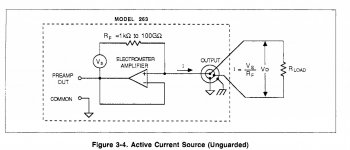
The is how the Keithley 263 calibrator (obsolete) creates a pA to mA current source. This is publicly available information. The op amp used is an OPA128. The DUT is ground referenced. The voltage source has ranges of 200mV, 2V and 20V.
I will give this a try when I can source the op amps.
I will give this a try when I can source the op amps.
Attachments
I have finalized the project:


For now, it looks reasonably stable; we will see in six months time. The accuracy is only 0.5 to 5%, depending on the resistance value: I wasn't maniac about the calibration, and anyway it is just a convenient, 3 digit workshop-type instrument, not a metrological device.
The common can be earthed, grounded or left floating (it is a class II device) which is very convenient when measuring earthed or bulky metallic DUT like a tank or a stationary device.
It has a guard terminal that can be used to float the DUT, and replicates the measured voltage=resistance, allowing a better resolution if required.
It is tolerant and easy to use compared to "real" instruments
There is still ~5pA unaccounted for in the CCS region, which I compensated with the current-setting resistor, but the rest looks pretty optimal: I made a test by first connecting the pico-ammeter directly in the foot of the input (that is GND side), then I inserted a ~80Gohm resistor on the hot side: the difference was in the region of 0.1pA, which shows that the output impedance of the CCS is more than high enough, and the input current/impedance of the follower is perfectly adequate.
I had tested these aspects beforehand, thus it comes as no surprise.
The TLC272 is not an electrometer-grade opamp, but selected samples can be quite good, and the pinout globally lends itself to this particular configuration, as there is a good degree of inherent guarding.
The PCB is heavily scratched/milled/butchered/notched, because that's where most of the problems came from, and if I make another pA/fA project (and I am going to make an ion chamber soon), that is something I will look at very closely.
The robustness regarding 50Hz noise is quite good, provided a minimum of precautions are taken: you can see on the pics that the "hot" terminal is a very short stub, meaning the DUT generally sits just above the front panel, which is made of copper clad connected to GND. The full scale voltage of 10V also helps (there is even a ~20% overrange margin)
As the input has its shield connected to the guard, an extension is perfectly possible without affecting the performances when measuring bulky or distant items.
The response time is reasonable, even on the 100G range: there is a 100K/82pF filter on the buffer input, but the charging time is acceptable.
Thus, for now everything looks good; what remains to be seen is the long term evolution: will the leakages remain stable?
It is a very cool project. Expensive DMMs that I have do not go past 1G. The resistors will definitely change value with age, voltage, temperature and humidity. Since you are only going to 10V the voltage coefficient will not matter much. For sure I witness temperature coefficient of large value resistors daily.
One of my cheap, 2kpts DMM has a 200Meg range, which is rare, even for top notch models, which is why I started at 1G. Adding a 100Meg range would have been easy, but it wasn't necessary.
I have also built a 1Tohm meter, but it is extremely demanding on its top range regarding shielding, guarding, etc., and none of the measuring terminals is grounded which adds difficulties and constraints.
This means that I only use it when I have no other option. By contrast, this gigaohmmeter is not as accurate and doesn't go as far, but it is almost as easy to use as a regular ohmmeter: you just need to take some basic precautions, and if you don't, the red LED calls you to order.
The principles could easily be translated into a better, more accurate instrument: use two electrometer opamps (they are not hugely expensive), good resistors, a good substrate and a layout that inherently rejects its imperfections. When unavoidable, use PTFE standoffs and inserts. And of course, test everything: even the humble reed relay I used for range switching had to be carefully selected among a large number of candidates. The one from Gunther came on top, and had negligible leakages
In your tera ohm meter, do you use the unknown resistor to charge a capacitor and measure dv/dt of the capacitor? I have been investigating commercial tera ohm meters and high resistance bridges.
The HP 4329A works like a traditional Ohmmeter measuring the current through the unknown (down to 20 attoamps) to measure high resistances (up to 20 petaOhm). The manual has some insights on test fixtures and dealing with stray leakages. https://www.keysight.com/us/en/assets/9018-05819/user-manuals/9018-05819.pdf
The Fluke 8060A also has a high resistance mode up to 300 MegOhms which is useful for finding leakage on PCBs.
The Fluke 8060A also has a high resistance mode up to 300 MegOhms which is useful for finding leakage on PCBs.
Wow! that's a completely different league...The HP 4329A works like a traditional Ohmmeter measuring the current through the unknown (down to 20 attoamps) to measure high resistances (up to 20 petaOhm). The manual has some insights on test fixtures and dealing with stray leakages. https://www.keysight.com/us/en/assets/9018-05819/user-manuals/9018-05819.pdf
The Fluke 8060A also has a high resistance mode up to 300 MegOhms which is useful for finding leakage on PCBs.
The short answer is yes. In reality, things are somewhat more complicated: it is all part of a specific A/D converter. In fact the ohmmeter is an A/D converter, or more accurately a resistance to digital converter. It saves one step in the processing, and there is no need for high value, accurate reference resistors.In your tera ohm meter, do you use the unknown resistor to charge a capacitor and measure dv/dt of the capacitor?
The conversion engine is rather smart and unusual: IIRC it is hyperbolic and works iteratively.
All of this is very smart and clever, but in practice it is not very pleasant to use: for large values, the converter needs a number of iteration steps to converge, because it creates its own timing, and when the instrument needs to recover from a severe under- or over-range, it takes even longer.
In addition, it doesn't like perturbations during the conversion, meaning the DUT has to be well-shielded for the 10G and higher ranges: the biscuit tin becomes unavoidable.
Also, it doesn't like too much unguarded capacitance in parallel with the DUT: it lengthens the process even more, and if it is too large, it derails it completely.
And finally, none of the test terminals can be grounded, which is inconvenient. This means that the measurements are limited to a fully floating component that can sit inside a box.
This is the beast:
It is of course useful, but in comparison the gigaohmeter is a pleasure to use. Of course, it doesn't have the accuracy, range or resolution of the teraohmmeter, but for 90% of the situations it is good enough
- Home
- Design & Build
- Equipment & Tools
- nA CCS mystery