Re: Well, I think you can keep the name
I used surface mount LEDs but there are also through holes (covered up by the LED) so you can solder in wires and run an LED to the front panel of a case if you'd like. The amp I sent Michael doesn't have a blue power LED because I ran out of that certain value of resistor in that specific size (doh). The other LED is tied to the fault pin of the chip. If you power down the 14V supply but not the 5V supply you'll see the orange LED light up. Don't worry, that won't hurt the amp but the turn on delay circuit doesn't work like it should when you power the 14V supply back up. I included the delay dircuit mainly for testing with these boards which is why there's also an option to jumper the mute to ground so it's unmuted all the time. That way you can just power up the 5V supply first to avoid the thump. Thanks for taking the time to review the amp!
The current Ref-T sounds just as good as the first Ref-T layout because there is more filtering on the supply lines for the 14V sections.
"Very strong, good bass, lots of low mid" in ghetto speak would be "It's got balls, yo." But like you and Art said, it doesn't lose any of the detail inherent to the Tripath chips. The whole point of the board was to bring out the best in the TA2021B with a minimally compromised layout (without using more than a 2 layer PCB) and good components.
Thanks for the compliment about the board. Don't forget that I have had a lot of practice soldering SMDs and winding toroids... These boards are even harder to solder because I didn't use thermals on the ground planes! That would have to be changed for production because it takes a lot of heat to get the continuous ground plane on this board up to temp.
Thank you for reviewing the amp as well. Don't either of you hold back on your reviews. We want the good, the bad, and possibly the ugly. If this thing isn't worth putting anymore time or money into then let me know asap so I can start saving for my retirement (maybe)
amt said:BTW Brian, the SMD LED on the board is a nice touch. Nice to know theres DC on the board once the PS is turned on.
I used surface mount LEDs but there are also through holes (covered up by the LED) so you can solder in wires and run an LED to the front panel of a case if you'd like. The amp I sent Michael doesn't have a blue power LED because I ran out of that certain value of resistor in that specific size (doh). The other LED is tied to the fault pin of the chip. If you power down the 14V supply but not the 5V supply you'll see the orange LED light up. Don't worry, that won't hurt the amp but the turn on delay circuit doesn't work like it should when you power the 14V supply back up. I included the delay dircuit mainly for testing with these boards which is why there's also an option to jumper the mute to ground so it's unmuted all the time. That way you can just power up the 5V supply first to avoid the thump. Thanks for taking the time to review the amp!
Yes, but you can only go so far with the Tripath chips. It seems you can only reliably separate the 14V and 5V supplies with the TA202X chips. I didn't have a problem separating the 5V analog and digital sections but the chip didn't like having the 14V driving section separated from the two output sections during power down with the 5V sections still on.serengetiplains said:The more "separate supply"d the better, ey?
The current Ref-T sounds just as good as the first Ref-T layout because there is more filtering on the supply lines for the 14V sections.
panomaniac said:Very strong, good bass, lots of low mid. Plus all the detail of the Tripath chip.
What 1st impressed me about the amp board was how well it is made. Beautiful work.
"Very strong, good bass, lots of low mid" in ghetto speak would be "It's got balls, yo." But like you and Art said, it doesn't lose any of the detail inherent to the Tripath chips. The whole point of the board was to bring out the best in the TA2021B with a minimally compromised layout (without using more than a 2 layer PCB) and good components.
Thanks for the compliment about the board. Don't forget that I have had a lot of practice soldering SMDs and winding toroids... These boards are even harder to solder because I didn't use thermals on the ground planes! That would have to be changed for production because it takes a lot of heat to get the continuous ground plane on this board up to temp.
Thank you for reviewing the amp as well. Don't either of you hold back on your reviews. We want the good, the bad, and possibly the ugly. If this thing isn't worth putting anymore time or money into then let me know asap so I can start saving for my retirement (maybe)

Hey Brian,
Do you have a preferred order for power up - power down?
I haven't figured out which to connect/disconnect first. 14V or 5V.
Do you have a preferred order for power up - power down?
I haven't figured out which to connect/disconnect first. 14V or 5V.
Michael,
The 5V first and then the 14V and then disconnect 14V and then 5V. I tried both at once and got the dreaded thump. But will the 5V first, I can barely tell the amps been turned on. I guess Brian gave me more instruction since Im more electronically challenged than you!
Art
The 5V first and then the 14V and then disconnect 14V and then 5V. I tried both at once and got the dreaded thump. But will the 5V first, I can barely tell the amps been turned on. I guess Brian gave me more instruction since Im more electronically challenged than you!
Art
Excellent work Brian!
I too am interested in a kit/PCB. I think you got a real winner here.
Keep it up!
-Ken
I too am interested in a kit/PCB. I think you got a real winner here.
Keep it up!
-Ken
Art, are you sure they were powered up at exactly the same time? The timer circuit senses when the 14V supply turns on and keeps the chip muted for about half a second while the coupling caps charge up. Half a second should be sufficient time for even fairly large values of capacitance. The amp is then unmuted and all you should hear is a click when the outputs become functional.amt said:I tried both at once and got the dreaded thump.
I'm sure there could be an easy way to implement a better mute circuit. I just haven't had time to think of ideas for one. They love to pile stuff on me at work cause I actually get stuff done... Maybe it's time to start slacking off a bit.
Haha! C'mon now Art, that isn't the case at all. I actually thought I sent Michael that bit of info but I guess I forgot to. Sorry about that panoamt said:I guess Brian gave me more instruction since Im more electronically challenged than you!

Thanks for the interest kec. As others have indicated, it seems that a small run would be the most desirable option and that's what I'm working on looking into. Thanks for the help from others on that front too! You guys have given me some good places to look at.
Just FYI, the amps seems to be very low noise - no hiss that I can hear. My guess is that is due to the good 5V section.
I have been running the 5V section from a 12V SLA battery. FYI - The 5V section draws about 25mA, too much to run it on a 9V battery for long. Too bad.
I have been running the 5V section from a 12V SLA battery. FYI - The 5V section draws about 25mA, too much to run it on a 9V battery for long. Too bad.
Technically there are two separate 5V sections that have a weak internal connection - analog and digital. They each have their own supply pin on the chip but I found that having them separated didn't have any audible improvement over having them tied together. The bypass cap right off of each supply pin takes care of any noise the regulator and bulk filter cap let through.
I found out about the 9V battery the hard way! You can get about a day or two of continuous idling and some music out of one before the voltage gets too low and you hear a horrible noise coming from your speakers.
I found out about the 9V battery the hard way! You can get about a day or two of continuous idling and some music out of one before the voltage gets too low and you hear a horrible noise coming from your speakers.
Brian, what do you mean that the 5V sections are separate but also have a weak internal connection? Must both pins be fed with a 5V supply?
Brian, If a production run ends up adding a considerable amount to the final cost of the amp; I would be very interested in a few "41hz" style kits that include all the parts needed. Soldering the chip to the board does not intimidate me at all.
Tom - The 5V analog and 5V digital sections on the chips are separate in that they have their own supply pins, but they have a weak electrical connection internally and must both be supplied with 5V. Say you wanted to use a separate supply for each 5V pin. If one supply voltage is different from the other one then current will flow through that weak electrical connection between the two pins. If too much current flows through the weak connnection then it will most likely burn up and could damage other parts of the circuit on the die. The same thing goes for the weak connection between the three 14V supply sections, only you're dealing with higher voltage and the potential for a higher current that could do more damage.
Anonymous - what would you consider to be a considerable amount? For a small run of 50-100 or so I'm anticipating a possible price of around $100 per amp. It all depends where the assembly would be done too. Either way, I'm sure a kit would be cheaper and I'll think about making some up for those of us who aren't afraid of little smd stuff. I'm afraid to go the kit route mainly because I don't have time to offer support for such a venture.
Anonymous - what would you consider to be a considerable amount? For a small run of 50-100 or so I'm anticipating a possible price of around $100 per amp. It all depends where the assembly would be done too. Either way, I'm sure a kit would be cheaper and I'll think about making some up for those of us who aren't afraid of little smd stuff. I'm afraid to go the kit route mainly because I don't have time to offer support for such a venture.
I haven't the first clue what assembly costs, but if it adds more than $10-$15 or so to the final cost I would rather assemble it myself. If I bought 3 or 4 amps then I'm sure the cost of the assembly would add up to a decent amount. Plus, after successfully completing 3 AMP1-B's; I find it very rewarding to do all the assembly myself.
I do understand how taxing support for kits would be though, just look at the 41hz forum. Its your project either way and the decision is ultimately yours.
I do understand how taxing support for kits would be though, just look at the 41hz forum. Its your project either way and the decision is ultimately yours.
I did some measuring and spectrum analysis of the Ref-T and 2 other T-Amps this afternoon. I will post graphs as soon as I can get them into a usable format.
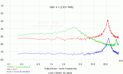
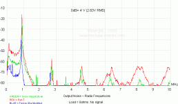
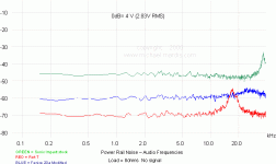
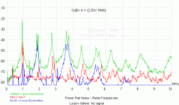
Not surprising is that the power supply rail of the Ref-T is the cleanest of the 3 tested. What was a surprise is that the Ref-T had the highest output noise of the 3. Highest in both audio and radio frequencies.
That is with the amp at idle, no input signal. Things will change a bit when the amp is under load. I'll do that testing tomorrow.
Amps tested were: the Ref-T, a modified Fenice 20a and a stock Sonic Impact 5066.
theAnonymous1 said:Brian, If a production run ends up adding a considerable amount to the final cost of the amp; I would be very interested in a few "41hz" style kits that include all the parts needed. Soldering the chip to the board does not intimidate me at all.
BWRX said:Anonymous - what would you consider to be a considerable amount? For a small run of 50-100 or so I'm anticipating a possible price of around $100 per amp. It all depends where the assembly would be done too. Either way, I'm sure a kit would be cheaper and I'll think about making some up for those of us who aren't afraid of little smd stuff. I'm afraid to go the kit route mainly because I don't have time to offer support for such a venture.
I'd just be happy with some PCBs. I can do the rest 🙂
-Ken
panomaniac said:Not surprising is that the power supply rail of the Ref-T is the cleanest of the 3 tested. What was a surprise is that the Ref-T had the highest output noise of the 3. Highest in both audio and radio frequencies.
That is with the amp at idle, no input signal. Things will change a bit when the amp is under load. I'll do that testing tomorrow.
The power supply rail better be clean! The two Panasonic FM caps with a ferrite bead between them are meant to keep a lot of RF junk from getting back to the regulator as well as provide a stiff voltage rail that can handle large transient current demands.
I can think of a couple reasons why the Ref-T would have more noise. First would be the output filter. It uses 10uH inductors and 0.27uF caps which are smaller than the nominal 0.47uF that most T-amps use. This raises the cutoff frequency of the filter and changes the Q as well. The other reason could be the ground plane. Switching currents could be flowing where I didn't want them to... That means there's still room for improvement! What's interesting is that I don't hear any noise when the amp is hooked up to my speakers and idling unless I put my ear withing half a foot of the drivers. That's just as good as any of the stock SI's or amp3's I've used.
I can't wait to see some plots! Thanks for taking some measurements Michael. By the way, what kind of spectrum analyzer do you have?
kec said:I'd just be happy with some PCBs. I can do the rest 🙂
Ken, I could sell you a blank PCB if you're interested! 😉 and a parts list of course.
I agree with Brian, the output filter may be the trouble on the output noise. But there is noise down in the Audio spectrum, too, where the filter should not have an effect.
That said; the amp is VERY quiet. Just want to show some measurements for comparison sake, and for Brian's amusement.
Let’s start with the output at audio frequencies. Click below. From this we can see that the Fenice and Ref-T have a similar noise signature, but the Fenice is 20dB lower. The Sonic looks different.
This graph shows left channel only. On the right channel the Ref-T had its noise bump lower, at about 13 kHz.
Attachments
All the measurements above were taken with a PicoScope digital scope.
You will see that 0dB is referenced to 2.83V RMS. Why?
2.83V RMS into 8 ohms is 1 watt. I used that reference because it is the standard used for speakers. This will give you some idea of how loud the noise might be on your system, whatever the sensitivity is.
This is NOT a S/N ratio. To get a good idea of that, you would need to drop at least 6dB, possibly 9dB. It would depend on how much signal each amp can put out before clipping..
- Status
- Not open for further replies.
- Home
- Amplifiers
- Class D
- My Ref-T amp


