I am starting my new DAC Kit project on diyaudio here.
I have already build many DACs over the past 7 years(although I am new here), I finally realized that I shall build a fully DIYable DAC KIT.
I am a audio electronic engineer and designing car audio equipment is my job. But I think these things are quite hard for DIY: to many tiny SMT components and to many QFN or BGA ICs. Also multi-layered PCB is too expensive for DIYer.
So I start a brand new design which shall be easy for DIYer as well as for me. Here are my principles:
1) DIP components are favored.
2) Less components.
3) All components shall be easy accessible from online disturbers such as DigiKey, Mouser, Elements14 etc.
4) No discontinued components(occupational habit), or although discontinued but easy accessible.
5) TOP grade performance.
Here is my structure of my DAC:
1) Input: Toslink,SPIDF,AES3 and USB 2.0 High Speed.
2) DIR: AK4113VF
3) Jitter cleaner: AK4127VF
4) System Controller: SST 8051 based mcu with 64K Super Flash(SST 89E516RD2)
5) DAC: AK4495S
6) LPF: Discrete OPAMP based LPF.
Now I have finished 1)~4)
I will post detailed explanation in the follow threads.
 Welcome to the forum. Please be aware that if this is a kit you are selling this thread will be moved to the commercial section.
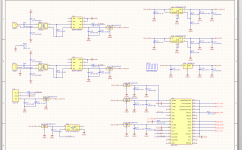
Here is the DIR part sch.
Initially I decide to use high speed OPAMP (AD8058) plus a ultra high speed compare (LT1712) to form a SPDIF amplifier. But I found this is way to complicated. A simple DS8921N will do the job. SN75157 is also OK, but follow my old test result, 75157 suffers from wave distortion, so DS8921 is the perfect choose.
Single powered SPDIF amplifier is usually sensitive to power rail noise. This is because the input is biased at the point half to power supply and the power rail noise will directly coupled to the input -> jitter! So I use TPS7A4501, a low noise LDO.
DSS1NB31H333 is a high performance EMI filter from Murata. The value 33000pf is carefully chosen due to the main working frequency of the digital ICs in a DAC is around 10Mhz~30Mhz.
So much for the input cicuit.")
Initially I decide to use high speed OPAMP (AD8058) plus a ultra high speed compare (LT1712) to form a SPDIF amplifier. But I found this is way to complicated. A simple DS8921N will do the job. SN75157 is also OK, but follow my old test result, 75157 suffers from wave distortion, so DS8921 is the perfect choose.
Single powered SPDIF amplifier is usually sensitive to power rail noise. This is because the input is biased at the point half to power supply and the power rail noise will directly coupled to the input -> jitter! So I use TPS7A4501, a low noise LDO.
DSS1NB31H333 is a high performance EMI filter from Murata. The value 33000pf is carefully chosen due to the main working frequency of the digital ICs in a DAC is around 10Mhz~30Mhz.
So much for the input cicuit.
Attachments
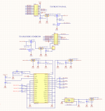
Here are the second part of the sch including the ASRC module and the MCU.
Nothing too special excluding the CCHD957 master clock.
In my previous experiments. ASRC always have some impact on audio quality. Good thing is the measurement results are quite pleased if ASRC is turned on. The IMD(Inter-modulation Distortion)usually reduced base on the quality of the master clock.
The bad thing is the fir filter(anti-imaging) usually have relative high ripple in the pass band and will have impact on the sound image.
Anyway, it is a trade off whether to use ASRC.
Also the front panel and the USB interface can be shutdown if not used.
See the attached pdf for a far more clear view of the sch
Attachments
- Status
- This old topic is closed. If you want to reopen this topic, contact a moderator using the "Report Post" button.