I am modifying a OEM car stereo head unit, I want to remove the internal AMP IC and add Pre-amp level outputs. after studying the circuit I have found this odd buffer/filter arraignment just before the TA8270HQ amp IC. From what I can tell, it is a slightly modified version of a Multiple feedback Low Pass filter?? I think....
The resistor values are as marked, and measured to verify. the capacitor values are as marked in circuit. the 2uF caps gave a fairly consistent reading but the 48nf cap may not be the correct value and the cap in the feedback path I could not measure in circuit. I will need to remove one of each of those parts and verify they values.
Some things of note, the + input actually goes to 1/2 vcc but for simplicity sake i just drew it as ground. its actually a network of 2x 3.9K resistors and a cap for the 1/2 vcc supply. all parts are SMD and all caps appear to be tantalum's.
The input is fed from the main audio processing IC to this circuit, then directly to the amp IC and out to speakers.
1- I am trying to understand the circuit and what it is there for.
2- I want to understand how to calculate the gain of the circuit.
3- I understand the purpose of the 2uf cap after the 3K resistor at the output but why the back to back 2uf caps after that??
4- what is the LF cut off of the circuit?
5- should I remove the filter or can I modify it for more gain?
Zc
Attachments
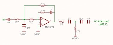
First cap is likely a coupling cap. It's not part of the MFB LP topology. After the op amp, the resistor and the "grounded" cap are another LP (1st order) filter stage. The last 2 caps may be part of the next stage or coupling caps.
The question I have is why is the 330R resistor there?
Do you have access to a SPICE modeler? This would be a good way to determine what the existing circuit is doing, gain , etc. Without knowing the missing cap value, you are kind of stuck... is there any way you can get the value. It's part of the FB network.
I can send you a spreadsheet that I built for designing LP MFB filters if that would be helpful for redesigning it. Send me a PM with your Email.
-Charlie
PS:
Gain at DC is equal to: R2/R1
where in this case:
R1 = 20k, R2 = 43k
So gain = 43/20 = 2.15 = 6.65 dB
Last edited:
I did a little playing around with my MFB design spreadsheet. It looks like the following is plausible:
gain = 2.15 times = 6.65 dB
corner frequency = 1000 Hz
Q = 0.707
C2 (your missing value) = 4.32 nF
The E96 series resistances then come out as you have shown them except the 12k, which should be 2.8k. Could you have read the code incorrectly?
-Charlie
gain = 2.15 times = 6.65 dB
corner frequency = 1000 Hz
Q = 0.707
C2 (your missing value) = 4.32 nF
The E96 series resistances then come out as you have shown them except the 12k, which should be 2.8k. Could you have read the code incorrectly?
-Charlie
well a corner freq of 1000 doesn't make much sense considering what the circuit is. that's puzzling. unless it is a shelving filter and they are rolling off at 1K or something??
The 12K resistor is a SMD device marked 123, which to me is 12-000, or 12,000 12K, I measured most of them just to make sure I was reading the numbers correctly.
There are 4 identical filters like this that the LF,RF, LR, RR audio signals go through to the 4 channel amp IC. So My guess was that this was some sort of digital filter after the processing IC. they use one large IC that does all the audio signal processing, tone controls, balance, fade and input switching and even D/A conversion. of course that IC is OEM only and no datasheets exist for it.
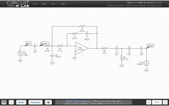
Once you figure out the missing capacitance, go to this web site and do an online circuit sim of the MFB portion of the circuit.
https://www.circuitlab.com/
https://www.circuitlab.com/
Ok well...IF...IF i did the sim correct then this is the results... a LP/HP filter with -3db down points of about 5khz and 30khz but what is more interesting is the 180 degree phase shift right in the middle of the plot??? i am very confused now...
Attachments
TI's filter pro is an excellent filter design package.
Active Filter Design Application - FILTERPRO - TI Software Folder
Active Filter Design Application - FILTERPRO - TI Software Folder
Ok well...IF...IF i did the sim correct then this is the results... a LP/HP filter with -3db down points of about 5khz and 30khz but what is more interesting is the 180 degree phase shift right in the middle of the plot??? i am very confused now...
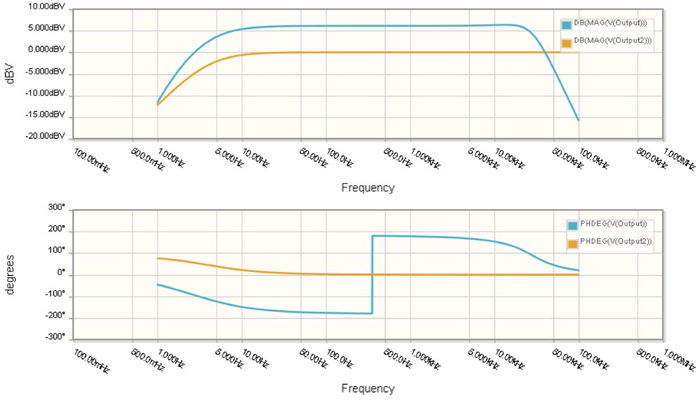
The phase shift is just a consequence of the plotting - the phase is continually decreasing. Typically phase angles are shown lying between -180 degrees and 180 degrees. When the value exceeds either limit it is "wrapped" back into that interval. In your case, the phase is slowly decreasing and finally passes below -180 degrees where you see the "vertical line" on the plot.
It's best to set the y-axis limits to 180 and -180 to see the phase behavior when it's wrapped in this manner.
-Charlie
- Status
- This old topic is closed. If you want to reopen this topic, contact a moderator using the "Report Post" button.
- Home
- Amplifiers
- Solid State
- Multiple feedback LP filter ?? Help??