I have this amp some what working now but it has a couple of issues.
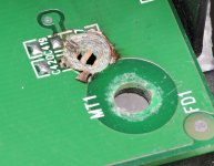
There was some physical damage done to the input caps and little transformer. I replaced the caps and transplanted a round transformer in from another amp. I marked the orientation of the transformer before removing it from the other amp denoting which side went to the drivers and which went to the PS FETs.
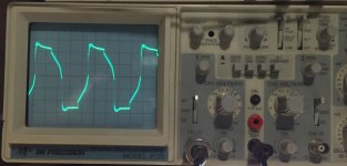
With the amp powered up, I get the measurements shown below (5V/div & 5uS). First one is taken at the base of an A56 driver. The second is taken from a transformer leg driving the gate of the PS FET. Seeing half of the amplitude of the drivers at the gates I thought I made a mistake installing the transformer so I rotated it 180 degrees with exactly the same outcome.
I have ~ +/- 14.5V at the op amps and -35.5V & 33.8V (too low?) at the rectifier's and no excessive current draw at idle.
The main problem with the amp is, while it produces clean audio, it clips at ~16VAC (no load) at the speaker terminal instead of an expected ~34.65VAC. I can repeat this consistently by either sending a strong signal in or by increasing the amplifier's gain control. Right now I have the jumpers in place bypassing the preamp board and the little transformer is still installed backward from my original marking.
Is this transformer incompatible or is it defective?
The other problem is the adjustable LED lighting isn't working, which we'll tackle last.
There was some physical damage done to the input caps and little transformer. I replaced the caps and transplanted a round transformer in from another amp. I marked the orientation of the transformer before removing it from the other amp denoting which side went to the drivers and which went to the PS FETs.
With the amp powered up, I get the measurements shown below (5V/div & 5uS). First one is taken at the base of an A56 driver. The second is taken from a transformer leg driving the gate of the PS FET. Seeing half of the amplitude of the drivers at the gates I thought I made a mistake installing the transformer so I rotated it 180 degrees with exactly the same outcome.
I have ~ +/- 14.5V at the op amps and -35.5V & 33.8V (too low?) at the rectifier's and no excessive current draw at idle.
The main problem with the amp is, while it produces clean audio, it clips at ~16VAC (no load) at the speaker terminal instead of an expected ~34.65VAC. I can repeat this consistently by either sending a strong signal in or by increasing the amplifier's gain control. Right now I have the jumpers in place bypassing the preamp board and the little transformer is still installed backward from my original marking.
Is this transformer incompatible or is it defective?
The other problem is the adjustable LED lighting isn't working, which we'll tackle last.
Attachments


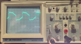
Switched scope back to DC coupling.
The probe placement remained the same as above but for the base of the driver, I changed the scope to 10V/Div & 5uS.
The transformer leg driving the FET is back to 5V/Div, 5uS.
I have 14.5V at the amp and I am not using a current limiter on it.
The probe placement remained the same as above but for the base of the driver, I changed the scope to 10V/Div & 5uS.
The transformer leg driving the FET is back to 5V/Div, 5uS.
I have 14.5V at the amp and I am not using a current limiter on it.
Attachments
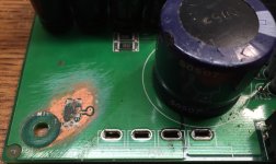
I replaced the two 10 ohm, base to emitter resistors at the drivers.
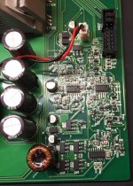
I replaced the eight 2200uF capacitors due to physical damage.
I replaced the transformer due to physical damage.
I installed the .47uF capacitor across the output terminal.
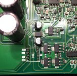
The previous work I saw was that of the sanded area around the missing surface mount capacitors and there was another sanded area under one of the 2200uF caps.
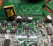
I see non-original solder around some of the PS FETs, but they all match.
I don't see anything else.
I replaced the eight 2200uF capacitors due to physical damage.
I replaced the transformer due to physical damage.
I installed the .47uF capacitor across the output terminal.
The previous work I saw was that of the sanded area around the missing surface mount capacitors and there was another sanded area under one of the 2200uF caps.
I see non-original solder around some of the PS FETs, but they all match.
I don't see anything else.
The original is beyond my repair.
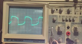
I removed the Sony transformer again. When I connect it to my frequency generator it's 1:1.
Wouldn't the secondary side always produce half of the primary with the pin configuration on this board using a 1:1?
The original looks like it is probably not a 1:1 but I can't know for sure.
I removed the Sony transformer again. When I connect it to my frequency generator it's 1:1.
Wouldn't the secondary side always produce half of the primary with the pin configuration on this board using a 1:1?
The original looks like it is probably not a 1:1 but I can't know for sure.
Attachments
- Status
- This old topic is closed. If you want to reopen this topic, contact a moderator using the "Report Post" button.
- Home
- General Interest
- Car Audio
- MTX Thunder 5601