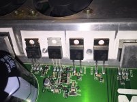
The Q401 Marked as 1DZ is defective for sure.
The Q405 Marked as C1URA is defective also (The base and emitter contact each other constant).
It broke the two A3120 Chips at location U403 and U402
Thank you for your reply before Perry Babin, are you sure those are the equivalent parts?
The Q405 Marked as C1URA is defective also (The base and emitter contact each other constant).
It broke the two A3120 Chips at location U403 and U402
Thank you for your reply before Perry Babin, are you sure those are the equivalent parts?
Perry Thanks for your fast reply.
The measured results from the C1URA are:
From Drain to Source: 28 Ohm and 27 ohm (going down)
From Drain to Gate: 5,12 Ohm
From Source to Gate 5,12 Ohm
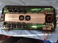
For those who are interested in the full story with pictures.
On my MTX 81001 are the following parts defective:
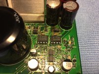
C406 marked as 35V 1000UF
C408 marked as 35V 1000UF
D404 marked as 1001
D405 marked as ES2D
D406 marked as ES2D
D401 marked as 831B
U402 marked as A3120
U403 marked as A3120
Q401 marked as 1DZ
Q405 marked as C1URA
The Led400 turns onn.
Also the "For Service Only" Led turn onn
The measured results from the C1URA are:
From Drain to Source: 28 Ohm and 27 ohm (going down)
From Drain to Gate: 5,12 Ohm
From Source to Gate 5,12 Ohm
For those who are interested in the full story with pictures.
On my MTX 81001 are the following parts defective:
C406 marked as 35V 1000UF
C408 marked as 35V 1000UF
D404 marked as 1001
D405 marked as ES2D
D406 marked as ES2D
D401 marked as 831B
U402 marked as A3120
U403 marked as A3120
Q401 marked as 1DZ
Q405 marked as C1URA
The Led400 turns onn.
Also the "For Service Only" Led turn onn
Attachments


Hello,
I replaced the following locations
C406 marked as 35V 1000UF
C408 marked as 35V 1000UF
D405 marked as ES2D
D406 marked as ES2D
D401 marked as 831B
U402 marked as A3120
U403 marked as A3120
Q401 marked as 1DZ
R410 marked as 1001
I recently also replaced Location R468 marked as 1000 and Location D409 marked as J5C.
After replacing these parts i decided to turn onn the amplifier with a 12V 2A adapter.
So i turned onn the amplifier and after 3 seconds i saw some smoke coming up from the area with location numbers C411, D404, R410 and the chip A3120.
Does someone know why the smoke is coming.
J5 is the marking for the part number. That converts to MMSZ5250B. Contact MTX if you want confirmation.
Until you get the regulators working properly, I'd suggest pulling the two 3120s and soldering a jumper connecting pins 5, 6 and 7 on each 3120. This will prevent damage to the opto-couplers and the jumpers will keep the outputs from switching on.
Yes. Look up the datasheet for the IRF540.
Until you get the regulators working properly, I'd suggest pulling the two 3120s and soldering a jumper connecting pins 5, 6 and 7 on each 3120. This will prevent damage to the opto-couplers and the jumpers will keep the outputs from switching on.
Yes. Look up the datasheet for the IRF540.
- Status
- This old topic is closed. If you want to reopen this topic, contact a moderator using the "Report Post" button.
- Home
- General Interest
- Car Audio
- MTX 81001, Want to know the value of two parts