Hi
Just getting my LM3875 to work properly ... sound is good ... but compared to my Gainclone LM1875 ... the LM3875 has more treble and less bass based on my listening ... isnt it normal ...?
How to get the Treble tamed down to balanced out the frequency response? ... Suggestions?
TQ
Just getting my LM3875 to work properly ... sound is good ... but compared to my Gainclone LM1875 ... the LM3875 has more treble and less bass based on my listening ... isnt it normal ...?
How to get the Treble tamed down to balanced out the frequency response? ... Suggestions?
TQ
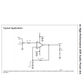
Schematic?
Bigger supply caps, bigger feedback caps, input pF decoupling, feedback compensation, output coil, etc.
But better amps normally have "more" treble (actually poorer amps lack the treble). When this treble can be reproduced without distortion, then you have the high-end sound. Distortion may come from cheap tweeter or inferior crossover. You may want to fix those, or kill the disturbing treble and be happy with med-fi.
Your design is missing many "optional" components that aren't optional. National/TI shows them later in the data sheet. Mostly things like the output inductor, damping resistor, and zobel network. Without these, you may get transient signal dependent oscillations that probably would brighten up the sound.
Another poster suggested of these kinds of amps, that if your heatsinks are too small, the chip temperature rises to the point where the Spike protection kicks in, which makes a sound rich in high frequencies.
You can get an idea of what kind of heatsinking is appropriate from the data sheet, or taking a look at an example amp build with LM3886s, which is a very similar chip.
Akitika GT-101
Note that this version shown is single supply, so no thermal washer is needed under the chip...this decreases thermal resistance, and keeps the chip cooler.
What rail voltages?
What transformer VA rating (per rail)?
What values of reservoir capacitance per rail?
What cap values are used for Cs?
If everything else is OK, you would also want Cs (local decoupling and bypass caps) to include 0.1 to 1 uF high-frequency bypass cap directly at each power pin, and also another 470 uF to 2200 uF (or more) for local decoupling, to be able to supply transient current demands with low-inductance (i.e. short length!) connections (preferably using three or more smaller paralleled electrolytic caps with values that sum to the desired total capacitance per rail, mounted as closely as possible the chip's power pins).
For your power supply, you should have a minimum of roughly 14,000 uF of reservoir capacitance per rail. That is based on calculating the capacitance required to be able to supply the current to produce a 5-Amp-peak sine wave at 20 Hz without causing the rail to dip by more than 1 Volt, assuming that sufficient-current recharging pulses are being provided every 8.3 ms (60 Hz mains; add 15% or so for 50 Hz mains). Using 3X 4700 uF would work nicely, for that.
But I would probably want roughly at least 3X 14000 uF per rail, which should be able to support 5 Amps DC current into 8 Ohms, continuously, for rails rated at 100 Watts RMS (40 Volts peak), without letting the rails dip by more than 1 Volt, assuming 120 Hz recharging pulses with sufficient current are available. That should cover almost any "worst-case" signal, at max output power.
For the equations, see the post at http://www.diyaudio.com/forums/chip-amps/152471-finalizing-tda2050-lm3886-2.html#post3363511 , which were explained and derived at http://www.diyaudio.com/forums/power-supplies/216409-power-supply-resevoir-size-169.html#post3320547 .
Your transformer VA (Volt-Amps) rating should be AT LEAST 1.5X to 2X the rated maximum RMS output power, just to account for heatsink losses (i.e. the amp is not 100% efficient). But I would use at least 3X the max rated RMS Watts for the VA rating, unless I had significant headroom in the rail voltage.
Cheers,
Tom
Last edited:
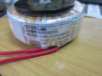
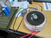
Power supply i am just using 4700uf for the positive and negative rail ... for the transformer i used a large toroid but i didnt know the VA rating because it didnt state on the transformer (it was actually salvaged from a broken amplifier i have)
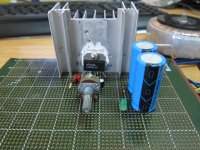
BTW here have some photos of the completed and working LM3875 amplifier i built
(it was actually salvaged from a broken amplifier i have)BTW here have some photos of the completed and working LM3875 amplifier i built
Attachments
But I would probably want roughly at least 3X 14000 uF per rail,
Well, if cost is not an objection ..... be my guest.
But what danny is using now is fine.
And the transformer looks big enough.
Pity out of the 80000 Chinese characters I still need to learn, oh, 79999?
So for now I can't read the transformer label .
Just give me some time.
Hey!!! I also understood the NUMBERSok ... there written was 22V 0V 22V ... another set of wire 22V 0V 6V but the latter set were not used since it was used by the previous broken amplifier for their unknown purpose ...
I though you would translate the Chinese Hanzi 汉字/漢字
Hey!!! I also understood the NUMBERS
I though you would translate the Chinese Hanzi 汉字/漢字
The Pinyin says "Happy building and listening, don't short live wire to chasis"
Well, if cost is not an objection ..... be my guest.
But what danny is using now is fine.
And the transformer looks big enough.
What he is using is fine for "not enough bass". I was operating under the asumption that he wanted his amplifier to be able to perform proper bass reproduction. Sorry if I misunderstood.
Actually, it might even be good-enough, capacitance-wise. I didn't calculate what it ought to be for his specific rail voltages.
There will be some degradation of the transient response, compared to the chip's specs, unless at least a small electrolytic is placed close to the power pins. Probably 220 uF per rail would be enough, if they were less than an inch from each power pin. But three parallel 68 uF per rail would be better.
Last edited:
Yeah, but why degrade the high end, and the transient response, when increasing the bass would be a better way to restore the relative tonal balance?
At least he could try increasing the caps to the minimum required to even be able to supply the current needed for the bass.
To the OP: You should realize that the real "signal path" is current from the caps, which is what directly makes the sound that comes from the speakers. See:
http://www.diyaudio.com/forums/power-supplies/216409-power-supply-resevoir-size-38.html#post3117390
Yeah, but why degrade the high end, and the transient response, when increasing the bass would be a better way to restore the relative tonal balance?
At least he could try increasing the caps to the minimum required to even be able to supply the current needed for the bass.
To the OP: You should realize that the real "signal path" is current from the caps, which is what directly makes the sound that comes from the speakers. See:
http://www.diyaudio.com/forums/power-supplies/216409-power-supply-resevoir-size-38.html#post3117390
it's a way of getting more bass; but he shouldn't need to go through all that!
The feedback cap so small does not affect the transient response in ANY audible way you might be able to measure a small change in slew rate but with the current capability of the output stage I somewhat doubt it.... However it will help kill off oscillations as will the earlier post quite correctly suggesting some token supply decoupler caps close to the IC power in pins
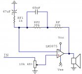
You could just add a bass boost like I did on one of my gainclones. It works just fine. Add a resistor and a small cap on feedback loop. Works just fine. Start with resistor RF2=10k ohm then increase the value, if you want more bass. You will need the feedback cap (47uF) to eliminate the DC offset at the output.
Regards
Regards
Attachments
No one asked what load your speakers are...
The lower the impedance, the more capacitance you should have on the rails. Gootee is on the right path, I would put some smaller capacitors very close to the power pins on the chip, and add more to the "bulk" end, at least another pair of 4700uFs.
Also, since you have built a DC coupled amp, it's possible DC from your source is reducing the low end of your speakers. At the very least you should add that "optional" feedback capacitor.
Last edited:
hi dannyjmf, may i introduce my thread for lm3875. http://www.diyaudio.com/forums/chip-amps/218873-my-non-invert-chip-amp-lm3875tf.html
1 where did you get lm3875t?
2 what are your speakers? is it suit for chip-amp?
1 where did you get lm3875t?
2 what are your speakers? is it suit for chip-amp?
1 where did you get lm3875t?
2 what are your speakers? is it suit for chip-amp?
The Chip LM3875 i get it locally from my country
My speakers are DIY speakers ... speakers are unbranded and purchased locally too ... tweeters used are cheap car tweeter ...
But comparison test shows there is more treble when using my LM3875 gainclone ... on the other hand ... it seems like the LM1875 have more bass and less treble ...
- Status
- This old topic is closed. If you want to reopen this topic, contact a moderator using the "Report Post" button.
- Home
- Amplifiers
- Chip Amps
- LM3875 gainclone too much treble