Hy,
I never built one so, It can be bad... real bad...
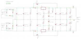
My first power supply would be this, for a lm4780 stereo, with type 3 power supply (+, GND, - one groud type). with a [SIZE=+1]200VA 2x28V/3,5A[/SIZE] toroid.
similar to :
http://www.diyaudio.com/forums/solid-state/10777-my-bench-power-supply.html
but I using a transistor to enhance the standard 1.5 Amp to 4, If its needed for the amp.
I think it's finished so the last step is to build it, but I'm not sure, so I'm open for any advice")
Thanks
I never built one so, It can be bad... real bad...
My first power supply would be this, for a lm4780 stereo, with type 3 power supply (+, GND, - one groud type). with a [SIZE=+1]200VA 2x28V/3,5A[/SIZE] toroid.
similar to :
http://www.diyaudio.com/forums/solid-state/10777-my-bench-power-supply.html
but I using a transistor to enhance the standard 1.5 Amp to 4, If its needed for the amp.
I think it's finished so the last step is to build it, but I'm not sure, so I'm open for any advice
Thanks
Attachments
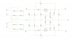
The AC mains voltage will vary within a range; depending on how conservative you want to be, you could estimate that it varies ± 10% or perhaps ± 15 %. The DC output voltage from the bridge rectifiers could be as high as (1.15 x 28VRMS) x (1.414 VDC/VRMS) - (2 x Vdiode). Numerically this is 43.5 volts.
So you may want to increase the voltage rating of C1, C2, C3, C6, C9, C10. Personally, I would choose 63V or 75V rated capacitors; your tastes may differ.
R2 and R3's values need to be interchanged. The "out" resistor is 240R, while the "gnd" resistor is 5K. Same mistake was made on R4, R5. 240R goes to output, 5K goes to gnd. Double check the IC regulators' datasheets; don't take my word for it. If you can make mistakes, so can I.
Another "personal taste" choice is whether to include, or omit, bleeder resistors across C9, C10, C13, C14. Something like 7.5K, 1/4 watt resistors would bleed the capacitors down to zero in two or three minutes, making the supply less dangerous for service personnel.
Finally, you may want to include LEDs and current limiting resistors on both supplies, just to help yourself when debugging / servicing the circuit. Are the fuses blown? Is the supply board actually powered up? Two green LEDs: yes!
Last edited:
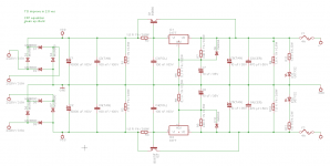
LM317 series needs a minimum load current of 10mA.
So R1 needs to be small enough NOT to turn on Q1 until the load current is well above minimum, say 100mA. R1 = 220R will leave Q1 permanently on and the output will not be regulated.
Also the 317 has thermal overload and current limit protection that works really well and you should use it. Calculate R1 to have driven Q1 on when about 1A is flowing in the regulator. R1 = 0R5 approx. This will give about one third to two thirds current share between the regulator and the pass transistor. Mount them closely on the same heatsink of course.
Personally I would use a much larger (eg 4700uF) output capacitor to increase the high frequency response capability. The regulator is notoriously slow and the output impedance becomes significant above 2.5kHz and is 10s of ohms from 10kHz.
Finally, the negative bridge rectifier is drawn back to front, but that's just a typo yes?
Good luck
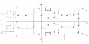
Your R1 and R2 were the wrong way round in the first diagram, I think, though you seem to have changed them in the second.
Is it too late to suggest you do the pass transistor as a CFP? There's still only one Vbe drop and it should give you a lower output impedance. And, if you've already got the power transistors then you just swap their positions around. You'll just need a resistor in series with the new driver transistors. If you've got LTspice then you can model it on that. Alternatively I'm pretty sure that the circuit is available on a JLH dedicated website. Google JLH power supply or John Linsley Hood and you'll find it with workable values. 68R will work anyway.
Is it too late to suggest you do the pass transistor as a CFP? There's still only one Vbe drop and it should give you a lower output impedance. And, if you've already got the power transistors then you just swap their positions around. You'll just need a resistor in series with the new driver transistors. If you've got LTspice then you can model it on that. Alternatively I'm pretty sure that the circuit is available on a JLH dedicated website. Google JLH power supply or John Linsley Hood and you'll find it with workable values. 68R will work anyway.
You changed the resistors which set the output voltage. Was that intentional? What output voltage do you hope to produce?
R11 and R12 set the current through the LEDs; the current seems awfully low. What LED current were you hoping to achieve? And why specify 1% tolerance on an LED current limit resistor?
R11 and R12 set the current through the LEDs; the current seems awfully low. What LED current were you hoping to achieve? And why specify 1% tolerance on an LED current limit resistor?
The LED resistors were corrected to a normal green one, and also the power regulator resistor was set to 240R that would give me around 28 V. I won't include CFP config for now, because I want to be sure that everything is works like it should be, but thanks for the advice .
And why specify 1% tolerance, because actually I didn't, for some reason that would cost less.
.And why specify 1% tolerance, because actually I didn't, for some reason that would cost less.
Attachments
Easter is almost here and I'm still not finished, but next week I will.
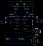
After fighting countless hours with eagle, there is the first pcb. The schematic is modified, but not much only the Graetz bridge... I will round every curve around 45 deg. The middle will be field with GND lead.
It's far from perfect the auto routing is really weird sometimes...
After fighting countless hours with eagle, there is the first pcb. The schematic is modified, but not much only the Graetz bridge... I will round every curve around 45 deg. The middle will be field with GND lead.
It's far from perfect the auto routing is really weird sometimes...
Attachments
- Status
- This old topic is closed. If you want to reopen this topic, contact a moderator using the "Report Post" button.
- Home
- Amplifiers
- Power Supplies
- LM series adjustable dual power supply