I wouldn't talk about "ideal impedance for a specific kind of tube", because changing the power supply voltage, or screen voltage, or local feedback kind and amount, or even the working class (AB1 vs AB2) will change the impedance to be chosen.
I have a pair of Toroidy 4k PP output transformers custom with 23%UL taps bought for a KT88/6550 project I've already posted here, but not yet built.
Tried it briefly and they sound good, but there's local feedback on the output tubes to "triodize" their curves.
I have a pair of Toroidy 4k PP output transformers custom with 23%UL taps bought for a KT88/6550 project I've already posted here, but not yet built.
Tried it briefly and they sound good, but there's local feedback on the output tubes to "triodize" their curves.
If you look at two transformers of equivalent construction and power capability, one 4.3k primary and one 6.6k, the 4.3k will have better high frequency extension and the 6.6k will have better low frequency extension. The 6.6k also results in better damping factor and usually less distortion (due to circuit factors independent of the transformer itself). If you use 6.6k you leave power on the table, but that’s up to you. Will you get a “better” 35 watts out of a pair of KT88’s vs a pair of 6L6 driving a given 6.6k trafo? Probably. The math favors it. Would you get a better 35 watts with a 6L6 quad instead? Now the emission capability is comparable (similar heater power) and the jury is out. It will get way more design and implementation dependent the more complex you make something.Yes, I've seen that most design use 4.3k or 5k transformers. As far as I can tell, this is so that you can obtain as much output power as possible. Based on my calculations, with a 6.6k transformer, I will get somewhere around 35W per channel. This is more than enough for my needs. Are there any other implications of using lower impedance transformers?
For the power transformer I was planning on using the TSTA 0220/001 if I go with toroids or the Hammond 370LX. This will imply an HT (B+) voltage of around 380Vdc. I'm aware that this means lower output power but this is ok as the amp itself is over-tubed. This will most probably improve reliability as tubes will not have to be replaced very often. At least that is my understanding.
You might consider the 373FX instead. The extra voltage will make a difference, and the tube life won't be effected if the design is sound.For the power transformer I was planning on using the TSTA 0220/001 if I go with toroids or the Hammond 370LX. This will imply an HT (B+) voltage of around 380Vdc. I'm aware that this means lower output power but this is ok as the amp itself is over-tubed. This will most probably improve reliability as tubes will not have to be replaced very often. At least that is my understanding.
The MA-1 version I'm building is based on the 100W UL version of the amp in this datasheet. https://frank.pocnet.net/sheets/084/k/KT88_GEC.pdf
I will use 560V B+ because I have it.
FWIW depending on where in the world you are, I have a used Hammond 278CX for sale. 100$CAD but the shipping for an 8kg box might be stupid!
OP, why don't you add one of these? I haven't ventured into valve assembly in years, but these auto-bias circuits are fantastic, at least on my Prima Luna. Perhaps they are just as efficient and would be worth a try.....")
https://www.audioamp.eu/
https://www.audioamp.eu/
+1 for those auto bias boards - They are fantastic! It's like Ronco again - Just set it and forget it™ I use the AB-4 in most of my designs. I don't like the AB-Q as much - especially if you use a design with a high peak current/idle current ratio. Just be careful if using AB-4 - The inputs are JFET and you can easily blow them up with ESD or a leaky soldering iron (that's why I now use my soldering iron powered from inverter/battery, and why Pavel builds my AB-4 modules using socketed DIP-8 opamps).
I'm in Romania so shipping will most probably be more than the transformer itself. I did look at the 373HX and this one will give a B+ voltage of around 493Vdc. Nice link with the GEC amplifiers. Will have a look at the document in more details. Thanks!You might consider the 373FX instead. The extra voltage will make a difference, and the tube life won't be effected if the design is sound.
The MA-1 version I'm building is based on the 100W UL version of the amp in this datasheet. https://frank.pocnet.net/sheets/084/k/KT88_GEC.pdf
I will use 560V B+ because I have it.
FWIW depending on where in the world you are, I have a used Hammond 278CX for sale. 100$CAD but the shipping for an 8kg box might be stupid!
This looks like an interesting piece of kit. I will most definitely look at these boards. Thanks!OP, why don't you add one of these? I haven't ventured into valve assembly in years, but these auto-bias circuits are fantastic, at least on my Prima Luna. Perhaps they are just as efficient and would be worth a try.....
https://www.audioamp.eu/
I prefer this one personally...
https://www.audioamp.eu/module-ab-4...he-amps-circuit-with-ttl-error-signal-output/
The other works well enough though.
I agree that there is a wide range of impedances, voltages and idle current that will give you good results. 6.6K is used as an example in many 6L6/5881 datasheets, and there is even a curve showing minimum distortion for the 6L6 in PP around 6K. It looks to me that 6.6K is kind of a "plug and play" value for the 6L6 family. Is that the only option? Of course not. Is it one that gives you a good result without doing a lot of experiments and calculations? Yes. 6L6GC, 6.6K PP UL OTP, 400...450V B+, 20~25W quiescent power. Always works.I wouldn't talk about "ideal impedance for a specific kind of tube", because changing the power supply voltage, or screen voltage, or local feedback kind and amount, or even the working class (AB1 vs AB2) will change the impedance to be chosen.
I have a pair of Toroidy 4k PP output transformers custom with 23%UL taps bought for a KT88/6550 project I've already posted here, but not yet built.
Tried it briefly and they sound good, but there's local feedback on the output tubes to "triodize" their curves.
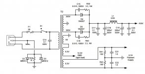
Just to give all of you some more info, in the design made by B. Cordell, he is using old output transformers with 7200OHM primaries and he also recommends another of the shelf alternative with a 4300 OHM primary. The only modifications required if we use the other transformer are the the resistors and capacitors connected between the grids and the anodes of the driver stage tube (12AU7). Bias of the output tubes is set to about 63mA and this will result in a voltage drop of about 200mV over the 3.16OHM cathode resistors. The power transformer is also an old one and it has 350-0-350 secondary that is full wave rectified to about 435Vdc when loaded to 330mA.
Solid state or tube rectifier? That's a quite powerful transformer...>350-0-350 secondary that is full wave rectified to about 435Vdc when loaded to 330mA.
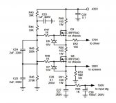
Solid state rectifier. An then a semi-regulated supply for the anode voltages of the input pair and the driver pair.Solid state or tube rectifier? That's a quite powerful transformer...
Attachments
A bit off topic, but I wonder if there is really a need for section regulated fonts etc?
We once compared the bass performance of a Crown PA power amp (I don't remember the model) that had a basic supply with a strong bridge rectifier and generous filter capacitors, against a Sansui BA2000 (I think) with a very heavy supply. elaborated and controlled to the maximum, and the tombs of the San sui seemed to be made of rubber... the speed of response of the source of the Crown made the difference, a point is reached in which the benefit of filtering so much looking for continuous DC is very doubtful. Just a reflection.
We once compared the bass performance of a Crown PA power amp (I don't remember the model) that had a basic supply with a strong bridge rectifier and generous filter capacitors, against a Sansui BA2000 (I think) with a very heavy supply. elaborated and controlled to the maximum, and the tombs of the San sui seemed to be made of rubber... the speed of response of the source of the Crown made the difference, a point is reached in which the benefit of filtering so much looking for continuous DC is very doubtful. Just a reflection.
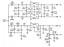
The general consensus is that the input stages are a lot more susceptible to low frequency noise (power supply ripple). This is valid for solid state amplifiers as well. I've build several of these solid state power amplifiers and I got to experiment with several topologies. The best results were with the ones where the input stage was well filtered. Especially the negative rail. You can clearly see the power supply frequencies on a spectrum analyzer. In the case of your test, maybe there were other differences as well. In my projects I had pretty significant differences between the THD+N (mainly noise) of an amplifier that had no filtering of the rails for the input stage and one that had plenty of filtering.A bit off topic, but I wonder if there is really a need for section regulated fonts etc?
We once compared the bass performance of a Crown PA power amp (I don't remember the model) that had a basic supply with a strong bridge rectifier and generous filter capacitors, against a Sansui BA2000 (I think) with a very heavy supply. elaborated and controlled to the maximum, and the tombs of the San sui seemed to be made of rubber... the speed of response of the source of the Crown made the difference, a point is reached in which the benefit of filtering so much looking for continuous DC is very doubtful. Just a reflection.
Based on the research I did and all the topics I read here and on other websites I'm inclining towards the toroidal transformer. It seems to have better performance (higher bandwidth and lower THD). There is another snag though. The toroidal transformers have a bit bigger footprint and that means that I will need a larger enclosure that will be able to fit all three transformers. This will increase the cost a bit. The Hammond transformers are a bit easier to fit. The problem is that if I go with the classic EI ones I will for sure want to make another project with toroids just so I can compare . This might not be a problem though
. This might not be a problem though - Home
- Amplifiers
- Tubes / Valves
- KT88 amplifier