Rodango, any comments on subjective sound ?
Well, let me see.
I'll be tweaking for sometime but for an out of the box product, I'd rate it exceptional.
But there is one thing I must do before I can really make a judgment and that is to get some 12AY7 tubes. I imagine that they'll sound better than the reject 12AU7s which I have been using...
Member
Joined 2009
Paid Member
I think its crazy how good my M77 sounds despite using reject 12AUs I'm looking forward to getting some 12AY7s as the budget allows.
One thing I'm sure we'd agree upon is the equipment we are running the M77 with makes a great difference:
CD Input > Yaqin SD32
LP Input >Pioneer PL-400
Amp > KT88 custom designed by Lance Cochrane, built by me
Speakers > Proac Tablett's
Wires > All high quality
One thing I'm sure we'd agree upon is the equipment we are running the M77 with makes a great difference:
CD Input > Yaqin SD32
LP Input >Pioneer PL-400
Amp > KT88 custom designed by Lance Cochrane, built by me
Speakers > Proac Tablett's
Wires > All high quality
It would be nice and useful to see how your M77 clones look like inside. Here is mine:
View attachment 1018584
Hi Tbaashus,It would be nice and useful to see how your M77 clones look like inside. Here is mine:
View attachment 1018584
Nice job!
I will soon be putting my version into a case but I am interested to know what connections you are making to the earth point at the centre of the PCB i.e. the four yellow, two green and one black wire?
Regards,
Gordon
Hi Gordon,Hi Tbaashus,
Nice job!
I will soon be putting my version into a case but I am interested to know what connections you are making to the earth point at the centre of the PCB i.e. the four yellow, two green and one black wire?
Regards,
Gordon
There are actually two black wires going from the earth point. One is ground connection for the line inputs (but not the phono inputs where I use shielded wires). I had a serious hum issue, and found that it disappeared when I grounded the PCB to the case, and that is what the second black wire is for.
I have recently repaired two Tandberg 6x tape recorders, and also have a 6x which was is such bad shape that I have used it as a parts machine. Six of the tubes on the amplifier boards on the 6x have metal shields connected to ground, so I just took the tube shields from the parts machine and put them in the M77 (connected with four yellow and two green wires). No idea if the shields make any difference, because I haven't tested the preamp without them. Anyway, there is very little noise in line amplifier and the phono preamp is also relatively quiet (not noticeable in practical use), so I don't think the shields did any harm.
Trond
Hi Trond,Hi Gordon,
There are actually two black wires going from the earth point. One is ground connection for the line inputs (but not the phono inputs where I use shielded wires). I had a serious hum issue, and found that it disappeared when I grounded the PCB to the case, and that is what the second black wire is for.
I have recently repaired two Tandberg 6x tape recorders, and also have a 6x which was is such bad shape that I have used it as a parts machine. Six of the tubes on the amplifier boards on the 6x have metal shields connected to ground, so I just took the tube shields from the parts machine and put them in the M77 (connected with four yellow and two green wires). No idea if the shields make any difference, because I haven't tested the preamp without them. Anyway, there is very little noise in line amplifier and the phono preamp is also relatively quiet (not noticeable in practical use), so I don't think the shields did any harm.
Trond
Many thanks, I did not see the tube shields when I first looked.....
Regards,
Gordon
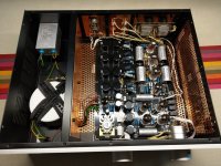
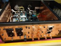
Finally got around to take some pictures of my build, please see attachments. I tried to use copper where possible, just like in the original 
Also, fully potted mains transformer attached with springs and foam, a line filter, and additional bypassing on the supplies (the small black film caps).
You can also see the MC input transformers on the backside, giving me both asymmetric and symmetric inputs. The symmetric outputs are connected asymmetricaly for the moment, work in progress..... The volume pot is a chinese stepped attenuator, works fine in my opinion.
The coupling caps are Jansen silver caps, and the RIAA caps are Silver Mica. Wiring is done with silver coated solid copper and cloth isolation.
Enjoy
Attachments
The rotary switch is in fact a 100k pot (+ 10k resistor), to adjust the input load for the MM input. And, as it is in parallel to the MC step-up transformer, it also works when the MC input is selected, here it will adjust from 100ohm to 1.1K.
On the bypass caps, I used 100nF, mostly because I had some with long leads that would nicely fit on top of the resistors without too much hassle. Next on the list was to make a 4-channel superreg (like the one from Allen Wright of Vacuumstate fame), one day I will get around to that project
On the bypass caps, I used 100nF, mostly because I had some with long leads that would nicely fit on top of the resistors without too much hassle. Next on the list was to make a 4-channel superreg (like the one from Allen Wright of Vacuumstate fame), one day I will get around to that project
Hi Zung, I should like to try your schematic in LTspice but I see that z.lib and ayumi.lib are missing.More clarification: the original RIAA is not very accurate, and the 2 caps that come with the kit are 10% polyester; they have their place in the trash bin.
I use 1% polystyrene, NOS from eBay, and LTspice to tweak the values of all 4 resistors: R15, R1, R8 & R13 in the attached schematic. Go slow, small increments, one at a time, or use the .step command if you know your way around LTspice.
Please, can you upload these library ?
Thanks a lot !
Sure.
I consolidated everything into z.lib, so you can delete or comment out ".inc ayumi.lib"; and you'll have to rename "z.txt" to "z.lib" and put it somewhere LTspice can find.
And here's a somewhat optimized version. As long as you're willing to mess with R1, 8, 13, 15 and C3, 4, you can get some pretty good results; series/parallel are OK, of course.
Attachments
just to be sure I understand, we are talking about the tube heater supply. The AC voltage at the transformer is 12.8V (as it should), and after the bridge rectifier (test point on the PCB) you are measuring 11.8V, correct?
Are all the tubes heating, in other words - is the phono section also turned on? And, have you tried adjusting the trimpot?
Are all the tubes heating, in other words - is the phono section also turned on? And, have you tried adjusting the trimpot?
Yes, at the control point 11.8 it was, the lamps were all warming up. I hammered one resistor 0.5 ohm, and it became 12.6, along with the phono. I left 3055, removed the capacitor from the base and instead put a 13 volt zener diode with a diode.just to be sure I understand, we are talking about the tube heater supply. The AC voltage at the transformer is 12.8V (as it should), and after the bridge rectifier (test point on the PCB) you are measuring 11.8V, correct?
Are all the tubes heating, in other words - is the phono section also turned on? And, have you tried adjusting the trimpot?
- Home
- Amplifiers
- Tubes / Valves
- Kondo KSL-M77 phono preamp clone project