I found different resistances on the output fets even know they are the same so I took them out and checked them and they seem to be ok I think. I get OL on every configuration except from pin 3-2 at 0.48v. So I put them back in and powered up the amp. It didn't go into protect so I tried playing it and there was no sound. I then took the two power fets out and checked them and I'm suspecting leaky gates but I'm not sure. When I check in diode mode everything seems fine but when I check in resistance from pin 3-2 one goes to 13.7m ohms and started to climb slowly 0.01m ohm at a time and the other one started around 14m ohms and climbed slowly too by 0.01m ohm. Then I checked again and one read 13.68m ohms and the other goes to 14.05m ohms and stayed there. Then I checked again and they both were over 14m ohms and they slowly started to climb 0.01m ohm at a time to around 14.35m ohms.
These seem like weird readings but I'm not familiar with leaky fets. They are DFP50N06 fets.
Thank you in advance
These seem like weird readings but I'm not familiar with leaky fets. They are DFP50N06 fets.
Thank you in advance
Last edited:
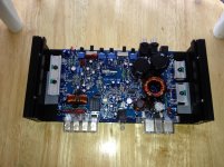
I just powered up the amp to check voltages at the Fet legs, her is what I got.
Power fets are the same:
Pin 1: 4.45v
Pin 2: 12.25v
Pin 3: 0.00v
Output fets are labeled the same:
Pin 1: -0.165v
Pin 2: 41.5v
Pin 3: -0.18v
Pin 1: -41.4v
Pin 2: -0.18v
Pin 3: -41.5v
Do these readings seem ok?
I checked the speaker terminals and they have -.163v in positive terminals and -0.003 v in negative terminals. The rca's have a little voltage on the inside and outside.
I appreciate any help you could give me.
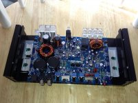
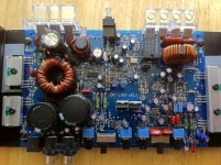
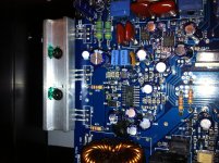
Here is the pic, I'll start checking what I can in that area. I checked the Zener diodes and I can get resistance measurements in both directions, do I have to take them out of the board to check them properly? Is it worth checking into or do you think the problem is something else? Thanks for your help.
Attachments
Last edited:
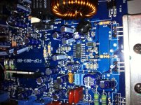
I think there was something on D56 that made it appear weird looking during the picture. it seems ok and after testing I don't think it's shorted.
Here are the voltages of the IRS2092.
Pin 1: 4.94v
Pin 2: -0.003v
Pin 3: -0.164v
Pin 4: 4.62v
Pin 5: 2.418v
Pin 6: -4.95v
Pin 7: -36.4v
Pin 8: -38.36v
Pin 9: -30.99v
Pin 10: -41.4v
Pin 11: -41.4v
Pin 12: -26.67v
Pin 13: -0.182v
Pin 14: -0.167v
Pin 15: -0.138v
Pin 16: -0.178v
Here are the voltages of the IRS2092.
Pin 1: 4.94v
Pin 2: -0.003v
Pin 3: -0.164v
Pin 4: 4.62v
Pin 5: 2.418v
Pin 6: -4.95v
Pin 7: -36.4v
Pin 8: -38.36v
Pin 9: -30.99v
Pin 10: -41.4v
Pin 11: -41.4v
Pin 12: -26.67v
Pin 13: -0.182v
Pin 14: -0.167v
Pin 15: -0.138v
Pin 16: -0.178v
Last edited:
Re-check the pin numbering.
http://datasheet.octopart.com/IRS2092SPBF-International-Rectifier-datasheet-10897912.pdf
http://datasheet.octopart.com/IRS2092SPBF-International-Rectifier-datasheet-10897912.pdf
That would tend to confirm that the IC has failed.
The only reference that I have is the datasheet and the reference circuit. Legs 1 and 3 of one of the output transistors should be connected to pins 10 and 11 of the driver IC.
What is the resistance between pin 11 and leg 1 of Q131?
What is the resistance between pin 10 and leg 3 of Q131?
The only reference that I have is the datasheet and the reference circuit. Legs 1 and 3 of one of the output transistors should be connected to pins 10 and 11 of the driver IC.
What is the resistance between pin 11 and leg 1 of Q131?
What is the resistance between pin 10 and leg 3 of Q131?
- Status
- This old topic is closed. If you want to reopen this topic, contact a moderator using the "Report Post" button.
- Home
- General Interest
- Car Audio
- Kaption DZ-300.1 help