
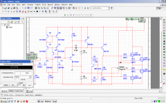
i was mistaken the vbe connection, now better now.
thd dropped to 0.001
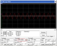
there is 64khz oscillation at the output but its not visible on the scope at all.
Note: there should be dc decoupling cap @ the output because at high temps vbe forces to the one side instead of regular vbes to the middle.
I think its possible to omitt the vbe and using Q11 (two functions) mounted on the heatsink as Vbe
thd dropped to 0.001
there is 64khz oscillation at the output but its not visible on the scope at all.
Note: there should be dc decoupling cap @ the output because at high temps vbe forces to the one side instead of regular vbes to the middle.
I think its possible to omitt the vbe and using Q11 (two functions) mounted on the heatsink as Vbe
Attachments
Last edited:
mosfet54,
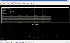
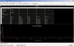
maximize the use of your multisim, use the grapher function there embedded more analysis of your circuit...ac analysis, bode plot, transient, fourier, open/closed loop response etc. It'll help a lot than just displaying the THD window.
BTW There are 3 ways to get the THD in Multisim, via display window, via grapher function-run transient analysis right click on the wave - choose click fourier, via grapher function-scroll select fourier - a table of harmonics will be shown.
Hope it helps!
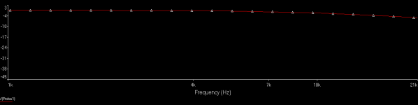
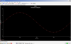
Thank you abetir, Here there are:
including zoomed AC analys + zoomed 64khz oscillation
its very small and i dont think its problem

Its <200nV
including zoomed AC analys + zoomed 64khz oscillation
its very small and i dont think its problem
Its <200nV
Attachments
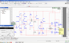
Firstly I tested without load..
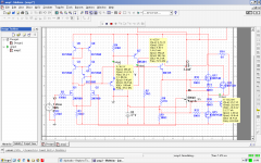
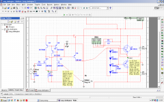
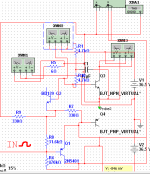
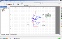
Here is updated sch and updated test.

i think i used badly the vbe in the 1st sch and omitted it in the 2nd.
i think there's no need of vbe at all because of the NFB correction.
its impossible to get thermal runaway because FB always corrects this. correct me if im wrong, if i am -> will add sziklai drive at the output and vbe instead class a low impedance stage.
p.s. No No, Im too stupid will add BD139 high power VBE but only if NFB cant correct this
AC analys is similar.
Here is updated sch and updated test.
i think i used badly the vbe in the 1st sch and omitted it in the 2nd.
i think there's no need of vbe at all because of the NFB correction.
its impossible to get thermal runaway because FB always corrects this. correct me if im wrong, if i am -> will add sziklai drive at the output and vbe instead class a low impedance stage.
p.s. No No, Im too stupid will add BD139 high power VBE but only if NFB cant correct this
AC analys is similar.
Attachments
Last edited:
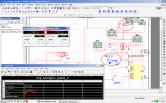
I successfuly designed a class AB darlington AMP with 250mA standby current.
I want to mention that bootstrapping is essential since it maximizes eff -> 2.9 times
with 20Vp-p 10Vp, 6 Ohm load and 7W out I get Power Dissip. of 17W for each transistor.
without bootstrapping this is 17*2.9 :OOO
I will use FN and FP 1016 darlingtons with maximum beta of 20k for the PNP and 30k for the NPN.
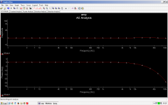
I get 0.00055% THD @7W . OPS is designed for +-36.5V because it will be used with LPT.
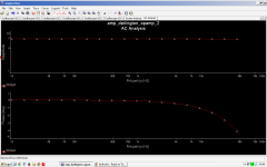
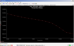
I think AC analys is good and LOOK AT 3RD PICTURE.
Vbe response. standby Bias current vs. temperature from 27dC to 150dC.
I think vbe is doing his job
clipping is good, clean.
P.S. Oh i should use BC556 instead 2N5401 since there are 45V max.
I want to mention that bootstrapping is essential since it maximizes eff -> 2.9 times
with 20Vp-p 10Vp, 6 Ohm load and 7W out I get Power Dissip. of 17W for each transistor.
without bootstrapping this is 17*2.9 :OOO
I will use FN and FP 1016 darlingtons with maximum beta of 20k for the PNP and 30k for the NPN.
I get 0.00055% THD @7W . OPS is designed for +-36.5V because it will be used with LPT.
I think AC analys is good and LOOK AT 3RD PICTURE.
Vbe response. standby Bias current vs. temperature from 27dC to 150dC.
I think vbe is doing his job
clipping is good, clean.
P.S. Oh i should use BC556 instead 2N5401 since there are 45V max.
Attachments
Last edited:
No, check datasheets for 2N5401/2N5551: Fairchild Semiconductor - datasheet pdf.....P.S. Oh i should use BC556 instead 2N5401 since there are 45V max.
Your threads seem to be more about you learning to use software properly and doodling an amplifier design. Simulation can't teach you much unless you begin with a solid knowledge of the problems with vertical Mosfets (hexfets) that aren't covered by simulation. You aren't making sense with efforts so far, so how about reading up on basic Mosfet Audio amplifier design requirements first, before scribbling out more flawed circuits. A cheap Ebay kit is a great start to learning how Mosfets work best and the way to achieving better things.
There are a lot of amplifier designs posted on beginner level forums everywhere. Very few will work for long in the real world at the rated power suggested, so please don't assume that anything a simple simulation shows to have low THD, is going to work properly. We are always interested in circuits that work but they need to be proven reliable by realistic load testing or proper thermal modelling first
If you don't usually read authoritative books or papers like Bob Cordell's, at least begin here: Using HEXFETs in High Fidelity Audio
Hi there, my design is successfull since i tried today. It sounds better than my mosfet one. it seems that i need low impedance driver for the fets. Simulation is not real, but its more real than u think !
I do know there are holes and am aware.
I like very much my vbe idea. its very simple and do the same job.
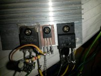
I listen to it and with this small heatsink it gets hot.
I tested my vbe idea in reality with hot heatsink and in the sim with analys graphic.
Will upload video because quality is good Im surprised.
I have two 220 Ohm 5W laying around and i think i should parallel them to use for makin' a class A amplifier
I do know there are holes and am aware.
I like very much my vbe idea. its very simple and do the same job.
I listen to it and with this small heatsink it gets hot.
I tested my vbe idea in reality with hot heatsink and in the sim with analys graphic.
Will upload video because quality is good
Im surprised.I have two 220 Ohm 5W laying around and i think i should parallel them to use for makin' a class A amplifier
Attachments
Last edited:
Well, that's what the signature says:So now we call you Darlington54?
Always different, always the same.
or if you prefer, use the YT user name:
or any other created by tapping the keyboard at random.jkshfjdshfk
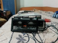
Wonder how his Mom let him test this high power amp, powered from a broken wall wart, and driving 2 2" speakers previously connected to 230V mains.
To the original question, 'is this good'.., the answer is NO.
Still no idea how to design a properly biased output stage, and I would bet my private parts that you have no idea why Q8 and Q9 were there (so you removed them later) in the first place, which is what happens when you copy other's designs without understanding them. BTW was your BD139 from the first and second schematic heat up a lot? I so wonder why....
You keep looking at things like distortion without looking at key points in your schematic to see if currents and voltages are behaving properly and what happens when say, the amp goes into clipping, or the power supply ripple is high. Somewhere in there is the reason why your output stage would self-destruct if used under continuous high output. Also, simulated Vbe multipliers often do not work the same in the real world, neither do distortion figures...
Also you have some very low quality equipment to test your amps quality. All the while, having higher quality equipment eight under your fingers - if only you knew how to use it for that task. It would be very revealing.
Last edited:
There is a horrible high pitched whistle in that video.
That pitch is from the TV and i dont know why.
If you want i will upload video without TV connected.
i see currents and voltages, see component max ratings too.
Also, simulated Vbe multipliers often do not work the same in the real world, neither do distortion figures...
Mine works perfect.
I heated up a lot and there is no thermal runaway.
Today i mounted bigger heatsink and volumed extremely loud.
my previous amp wasnt good at extreme high volumes but this is.
I was
that the heatsink was COLD. Only very little warm. very very littleMaybe this is from the bootstrapping.
Last thing todo is LTP input to reveal the full potencial of the PSU.
- Status
- This old topic is closed. If you want to reopen this topic, contact a moderator using the "Report Post" button.
- Home
- Amplifiers
- Solid State
- Is this good ?