")
welcome, the circuit reminds me of the maida regulator....http://www.diyaudio.com/forums/tubes-valves/209067-21st-century-maida-regulator.html
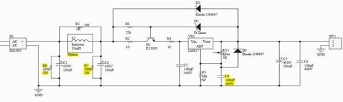
the zener could be a 27volt one, together with the mje13005 ensures that the vin-vout rating of the lm317 is never exceeded....
You are completely right!
 You are dissipating at least 2.35W in that resistor, which should be at least 10W for good thermal stability.
Use a fixed resistor between out and ref which should not be more than 1.21K if you want good regulation. (1mA of reference current) You could use a 392K + 7.87K if you need ~400V out. If you need to make the output voltage adjustable the pot should be placed in series with these resistors. Note that the LM317 can require as much as 10mA of load current to regulate correctly depending on maker, so make sure that the load current is sufficient when the load is warmed up.
The accuracy of the LM317 is sufficiently good that with 1% resistors you should be able to get close enough to the target output voltage without trimming.
Note that 100uF capacitor on the reference terminal is not a great idea, I'd not make it more than a few uF at these operating voltages. Don't expect the regulator to survive a short on the output either.
Does it actually work at all? I really don't see how you could subject an LM317 to these voltages. How could you send AC straight through a 10mH inductor? What happens if you put 100uF straight over AC? Where does the DC come from? Etc.
Actually I don't use any inductor
I'll echo what KevinKR and Sofaspud said. A 3W resistor with a constant 2.4W load it will most certainly run hot.
Since you have the pot for adjustment, the 68k value isn't that critical. Series and/or parallel several resistors as needed to get something close to 68k with at least a 10W equivalent - you should run a lot cooler then.
RF Dude
Since you have the pot for adjustment, the 68k value isn't that critical. Series and/or parallel several resistors as needed to get something close to 68k with at least a 10W equivalent - you should run a lot cooler then.
RF Dude
You also might want to increase the breakdown voltage rating of C4 - using a 400V cap across a 400V potential is a bit sporty...
If you put caps in series to increase the breakdown voltage, you will want to use equalizing resistors - a simple solution would be to stack a couple of 5W 33k resistors in series and put one 0.22 250V cap across each resistor. Digi has TDK 0.22uF, 250V caps, P/N FK20X7R2E224K in stock at 0.73 ea. - this will give you a 0.11uF 500V equivalent for C4 which should be plenty safe.
If you put caps in series to increase the breakdown voltage, you will want to use equalizing resistors - a simple solution would be to stack a couple of 5W 33k resistors in series and put one 0.22 250V cap across each resistor. Digi has TDK 0.22uF, 250V caps, P/N FK20X7R2E224K in stock at 0.73 ea. - this will give you a 0.11uF 500V equivalent for C4 which should be plenty safe.
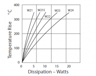
The better resistors tend to have temp rise graphs in their datasheets to give you an idea as to how hot they will get. Attached is an example from this http://www.farnell.com/datasheets/1449996.pdf welwyn datasheet.
Tony.
Tony.
Attachments
I must be in full design review mode... Occupational hazard, I guess.
Looking at the schematic further, my comment above on C4 also applies to C3 and C6. C6 is running right at its rated limit, and C3 is likely seeing a voltage above its rated limit sitting at the input to the LM317.
I would definitely use higher voltage rated caps for both of these - you risk blowing the caps as the applied voltage is going to stress them over time.
OK, just a few more things to chew on - good luck with the supply, hope you get 'er running happily and can move on to other parts of the design.
Last edited:
I must be in full design review mode... Occupational hazard, I guess.
Looking at the schematic further, my comment above on C4 also applies to C3 and C6. C6 is running right at its rated limit, and C3 is likely seeing a voltage above its rated limit sitting at the input to the LM317.
I would definitely use higher voltage rated caps for both of these - you risk blowing the caps as the applied voltage is going to stress them over time.
OK, just a few more things to chew on - good luck with the supply, hope you get 'er running happily and can move on to other parts of the design.
Tks for the input
I will replace all the capacitor with more higher rating maybe like 630V
Also for resistor, i just checked there is 68K at higher watt like 14W at digikey
Hi guys,
just want to give update
I am ending up changing Resistor 68K with Caddock 14W and change all capacitor with 1000V from Digikey
What a big different. The sound is more smooth.
So I believe what ever comes out from PS to any board (ex PA or pre-amp board) will effect the quality of the board itself
i learn some thing here tks guys
- Status
- This old topic is closed. If you want to reopen this topic, contact a moderator using the "Report Post" button.
- Home
- Amplifiers
- Power Supplies
- Is there any thing wrong with this design