Check out this little circuit! Any comments would be helpful as i intend to try this one out soon. It should be about 60w into 8ohms, and runs at 50khz. Notice the lack of output inductors?!? Should one be included even though the designer did not? There is a 'pulse shaping network' that looks like a zobel or snubber there, but...
Attachments
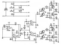
1) I would choose a faster slewing opamp than the TL074.
2) Yes, an output filter will be necessary, if you plan to run your speaker wire more than a few inches (to prevent EMI)
3) Since +/-51 volts is way too high for a common linear regulator dual (LM317, LM337) without some pre-regulation, at the very least buffer the zeners with an emitter follower.
4) Much has been written about half-bridge topologies pumping the power supply. Don't know how serious this issue could be, but something you must be aware of.
I intend to use this for a small sub, and will mount the amp very close to the speaker, possibly allowing operation without an inductor. I may include an inductor, anyway, in the form of a 6db lowpass crossover at about 150hz. The power supply is labelled funny; it is really 51v total, +/-25.5v. Can an amp like this be bridged across the load (high enough impedance, of course) or would it be unstable in that configuration? I planned on just feeding an inverted signal to one channel. The circuit, BTW is from popular electronics magazine years ago, but I found it in a compilation of circuits in book form.
Hi, Fredos,
I'm looking for adjustable deadtime, but with comparator front end. UCD is adjustable, but it is discrete. I wanted to use fast comparator.
From my experiment, this one has too little dead-time, making cross-conduction when the mosfets are hot. There are phases where both mosfets conduct. I can only change a the supply for the totem pole (+/-10V) to adjust a little, but that's it.
Attachments
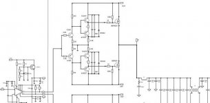
 After such a passive dead time adjustment (making the square wave not square anymore), do we need a square shaper (schmidt trigger or digital buffer) to reshape the square wave before reaching mosfets?
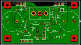
Update
The circuit seems to work ok as drawn, but can clearly be improved upon. The first 'upgrade' I will try is a faster opamp, b/c my layout is for a quad package. If this is not satisfactory, I may redo the layout to allow seperate triangle gen opamps and comparator. The switching freq is so low (50khz) that a 'faster' comparator may not squeeze any more out of the design, IMHO. In the text accompanying the original schematic it tates full range operation to 60w in 8 ohms. Off the top of my head, 51v is not enough to quite get there into 8 ohms. Also, 50khz switching does not seem reasonable for full range use. To me, these limitations are acceptable as I am attempting a very small subwoofer with a linkwitz transform eq, which brings me to my next questions:
Keeping in mind the low switching freq, mount the amp right next to a SHIELDED subwoofer and use shielded cable for the few inches to the terminals, and I think I may just get away without using an output filter...
I expect there are a few things to spoil this plan, like heating in the voice coils of the woofer. Any thoughts on this?
Trev,
Thank you for offering your expertise. What looks off to you in the original schematic? I have tried the circuit on low power rails, seems to work, could use some improvement. I really like the use of super available cheap parts in this schematic, as I would like to be able to make many of these little amps from parts in my bin.
Thank you for offering your expertise. What looks off to you in the original schematic? I have tried the circuit on low power rails, seems to work, could use some improvement. I really like the use of super available cheap parts in this schematic, as I would like to be able to make many of these little amps from parts in my bin.
Can you be more specific when you say it requires improvement
And alsio what were the supply rails you tested at?
I am unable to assist at the moment due to excessive peronal committments however these should clear up within a few weeks I am reelly interested in this project and will be to assist then
And alsio what were the supply rails you tested at?
I am unable to assist at the moment due to excessive peronal committments however these should clear up within a few weeks I am reelly interested in this project and will be to assist then
- Status
- This old topic is closed. If you want to reopen this topic, contact a moderator using the "Report Post" button.
- Home
- Amplifiers
- Class D
- Interesting schematic