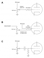
A question about connecting an RCA jack to the input triode. I'm all for experimenting, but would going from classic pattern A to alternative wiring B be would be bad sounding or unsafe?
In B, the upstream leg of the 100 K pot is replaced by a 50 K resistor that also replaces the grid stopper, and a return path is wired to the ground half of the pot.
In B, the upstream leg of the 100 K pot is replaced by a 50 K resistor that also replaces the grid stopper, and a return path is wired to the ground half of the pot.
Attachments

B, as Mooly says, removes the grid stopper at minimum volume. Not a good idea.
A, although popular, has the disadvantage that it puts grid current through the pot wiper which will eventually lead to noise problems.
Better to do C: like A, except that there is a grid leak resistor to ground and a coupling cap between the wiper and grid. No DC on the wiper so low noise. Subsonics removed by the cap so less IM. When the pot fails the valve is not left without bias.
Thank you all for your replies.
dgta: What I hoped to accomplish was a cleaner signal path, by way of reducing the number of series resistive elements.
Mooly, DF96: "...the grid stopper is shunted out at minimum volume" - Aha! Thank you for pointing that out. All the more important since this would be an 6922 tube. Drawback #1.
Ian: you're right. That's drawback #2.
DF96: I have added your suggestion to the schematic. Would it be OK to ground the grid leak resistor at the same point as the pot? Am I right in thinking the value of this resistor should be kept small if mute attenuation is to be achieved?
Attachments
Answering my own question about the value of the grid leak resistor: in C, at minimum volume, the equivalent resistance from (wiper to ground) + (grid leak resistor) wired in parallel tends to zero. Therefore full signal attenuation should be achieved regardless of the value of the grid leak resistor. As in B, though, input impedance is non-constant.
B, as Mooly says, removes the grid stopper at minimum volume. Not a good idea.
A, although popular, has the disadvantage that it puts grid current through the pot wiper which will eventually lead to noise problems.
Better to do C: like A, except that there is a grid leak resistor to ground and a coupling cap between the wiper and grid. No DC on the wiper so low noise. Subsonics removed by the cap so less IM. When the pot fails the valve is not left without bias.
I puzzled over DF96 saying "C"
I don't see that in the first post. Just A and B
I added C, via a virtual drawing. The OP has drawn it in his post 6, although without a grid stopper.
The input impedance will be roughly constant, as the valve and its grid leak resistor will normally be much higher in impedance than the volume pot. Assuming a sensible source, some variation doesn't matter anyway.
No, any decent cap will have low losses so no good for damping RF resonances. You need a grid stopper resistor in series with the cap (at the grid end, of course).Jhm said:true, C is stopperless, but the capacitor might provide the HF filtering that a resistor would.
The input impedance will be roughly constant, as the valve and its grid leak resistor will normally be much higher in impedance than the volume pot. Assuming a sensible source, some variation doesn't matter anyway.
I've added the grid stopper in C and here's the amended drawing. It's ironic how this started as a simplification study and ended up adding a capacitor and a grid leak resistor to the original design in A ")
I see the point of the capacitor in removing DC at the wiper but in this upstream position of the signal path, I expect it will impart a strong signature on the sound and should be chosen with care.
I see the point of the capacitor in removing DC at the wiper but in this upstream position of the signal path, I expect it will impart a strong signature on the sound and should be chosen with care.
Attachments
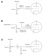
Thank you, Ian and DF96, that's good to know. The circuit is designed for 6922 and 6n1p tubes, with max grid resistances of 1 Mohm and 0.5 Mohm, respectively (cathode bias). For a ballpark figure, 0.022 microF cap plus 430 K grid leak resistor would give a -3 dB point of 17 Hz, if I'm not mistaken.
The cap that filters the audio input signal will have significant AC voltage across it.
When a cap has significant AC voltage across it, then the cap parameters will affect the signal.
When the cap has no significant AC signal across it, then the parameters have virtually no effect on the signal quality.
i.e set the input filter to F-3db=30Hz and the filtering cap will affect the sound quality.
Set the input filter to F-3db= 1.5Hz and the filtering cap has no effect on the audio signal quality.
Similarly for the RF filter. Set it high enough to have no effect on the sound quality but beware setting it too high to be effective in attenuating the RF you need/want to stop.
Last edited:
+1 and a ½But bear in mind that something somewhere in your system will set the LF rolloff. It is best to do this with a reasonable quality cap at a low signal point, rather than something out of your control at the power end of things.
- Status
- This old topic is closed. If you want to reopen this topic, contact a moderator using the "Report Post" button.
- Home
- Amplifiers
- Tubes / Valves
- Input wiring question