In the depths of these forums I chanced upon a time expired (I think) American
patent (1978) for a balanced enhanced mode MOSFET output power amp using an autotransformer..Cost has never figured much in pursuit of quality so the seed of a project was born.
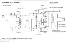
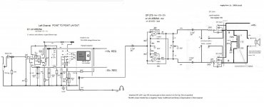
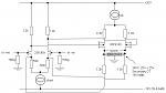
Class A is mandatory.I am trying to keep it simple and I don't need more than 25W per channel. A line level SE input followed by a differential balanced converter is incorporated.
Heres my very preliminary schematic. Please contribute suggestions/warnings etc and perhaps some clever contributor might sim it.
patent (1978) for a balanced enhanced mode MOSFET output power amp using an autotransformer..Cost has never figured much in pursuit of quality so the seed of a project was born.
Class A is mandatory.I am trying to keep it simple and I don't need more than 25W per channel. A line level SE input followed by a differential balanced converter is incorporated.
Heres my very preliminary schematic. Please contribute suggestions/warnings etc and perhaps some clever contributor might sim it.
Attachments
Last edited:
What performance improvements does the output transformer bring to the amplifier?
greetings Andrew
If it balances ok the amp allows a single supply with no output coupling capacitor. Some constructors (not me) think this very advantageous.
I tend to avoid split supplies because a power rail failure gets so messy.
It also has the inherent noise rejection properties of a balanced power output.
I was looking at Michael Rothacher's article (Dec 2011) in DIYAudio entitled
"L'Amp:A simple SIT amp.
My post has a similar power stage but in follower configuration.
Assuming 2SK82 and IRF Z44N have ball park similar specs;
Michaels load line graph shows potential Id of about 3.5A at Vg +6.5
and Vsd +30v.
I was a little concerned that since the inductor reactance is directly proportional to frequency, that the low audio frequency response may fall off badly. But I remembered that the output impedance includes the 10R (series) and 8R speaker (parallel) resistances that modify the frequency response.
In fact Michael measured a respectable -1.12dB at 20Hz and -1.72dB at 6okHz for L'Amp. It looks like a case of "suck it (and tweak it) and see".
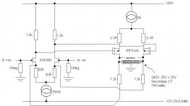
Perhaps I misunderstand you Abraxalito. The MOSFETS are in class A push-pullIts not an output transformer, rather the autoformer looks to be used as a balanced (current cancelling) choke load for the FETs. A choke loaded classA can in theory reach 50% efficiency, as against normal SE classA at 25%.
and there is no current cancelling at any point in the autotransformer.
It is correct to say that the 10R and speaker resistances will reduce the
efficiency of the amp, but this is of little significance to me.
Apart from supressing turnon thumps, the autotransformer output is also arguably less fault risk when direct coupled to expensive speakers.
Sloblo rail fuses are assumed in all cases, but can allow surge damage.
All sorts of mayhem ensue from component fail in split supplies (hence complicated protection and relays).
Autotransformer fail is very unlikely under any above circuit fail conditions.
Worst case is probably (unlikely) s/c fail of 10R resistor. The s/c current will follow the (milliohm) path of the autotransformer windings with perhaps a few milliamps thro the speaker coils.
Either or both MOSFET fail should not be a problem.
If the 10R resistor goes o/c there is no danger to the speakers.
The MOSFETS are in class A push-pull
and there is no current cancelling at any point in the autotransformer.
Perhaps 'current cancelling' wasn't the best choice of words but it looks to me like given the CT there will be no DC flux in the trafo. The DC flux from one side will be cancelled by that in the other because its in the opposite direction. A bit like the operation of a common-mode choke.
If your speakers are excruciatingly expensive you could consider a separate in line fuse with this schematic.
The amplifiers all being followers 4v rms in gives approx 4v rms out.
Max signal current to speakers is thus 500mA rms.
To guard against fault exposure across the speaker connections to +30v., place a 500mA sloblo fuse in a speaker lead for each channel.
The autotransformer can still carry 3A QC bias DC.(suggest a 5A sloblo rail fuse).
Belt and braces
Funny to see this is patented. I built an autotransformer amp class ab with 2xBUZ11 in the eighties that works in my guitar amp since. The reason for this topology was the output voltage swing, which is twice compared to a full bridge. With 12V car battery supply this yields about 30Watts into 8 Ohms.
I wound the autotransformer using M85 core and 2mm copper wire, that was a strong job I do not forget")
I wound the autotransformer using M85 core and 2mm copper wire, that was a strong job I do not forget
Attachments
Last edited:
500mAac to the speaker is equivalent to 2W into 8r0.
Surely the speaker current is MUCH greater than 500mAac.
Point taken Andrew, looks like the amp may need more than 4v. rms input to drive it to full output.
I'm thinking 12v. rms in and a 1.5A speaker fuse at 18W. output.
That is moving in the right direction.Point taken Andrew, looks like the amp may need more than 4v. rms input to drive it to full output.
I'm thinking 12v. rms in and a 1.5A speaker fuse at 18W. output.
18W into an 8r0 resistive test load is equivalent to 2.12Apk
That will pass an F2A fuse without rupturing it.
Expect an 8ohms 2way reactive speaker load to demand even more current from a 18W amplifier.
progress
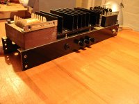
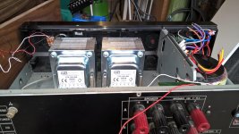
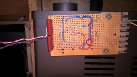
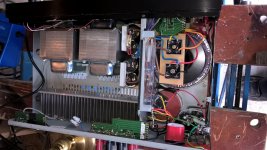
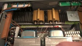
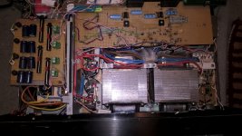
I cleaned out an old Sony amp for this project. See pics
Now squeezing a quart into a Sony pint pot.
I now have plus and minus 15.0v reg. for the opamps and
two plus 45.0v. for the Mosfets.
I decided to add a two stage buffer/preamp and a dedicated headphone amp.
I also found a nice chip se to balanced converter circuit that is pleasingly symmetrical.
Attachments
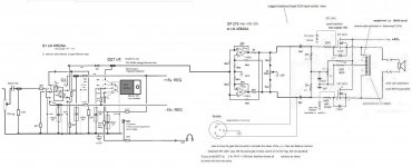
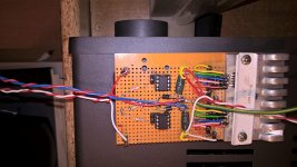
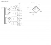
I was unable precisely to set gs bias with resistor network from +45v supply, even with precision pot and shunt diode regulator.
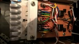
So I installed a +16.8 v. regulated floating supply (no earth ref) with a bridge for each gate.(diag attached)
This allowed each gate to be adjusted to 2 dec. places.
Gate to Source bias is tricky because there is less than a volt between threshold and saturation. Occasional tweaks were necessary to reduce hum to inaudible.
My rough estimate is about 25W maxed. Bass is good and treble maybe a tad harsh.
The lowest tolerable load was 41R and this was too hot to touch.
This amp will never be commercially attractive due to weight and cost, but it was an interesting build.
Attachments
Last edited:
I think an inductor output power amp is a great idea. In fact, I built one 15 years ago and its been in daily use ever since. My own DIY gear is all balanced, but it runs just fine with single ended input from my blu ray player.In the depths of these forums I chanced upon a time expired (I think) American
patent (1978) for a balanced enhanced mode MOSFET output power amp using an autotransformer..Cost has never figured much in pursuit of quality so the seed of a project was born.
Class A is mandatory.I am trying to keep it simple and I don't need more than 25W per channel. A line level SE input followed by a differential balanced converter is incorporated.
Here's my very preliminary schematic. Please contribute suggestions/warnings etc and perhaps some clever contributor might sim it.
http://www.diyaudio.com/forums/solid-state/212424-balanced-class-fet-amplifier.html
Attachments
- Status
- This old topic is closed. If you want to reopen this topic, contact a moderator using the "Report Post" button.
- Home
- Source & Line
- Analog Line Level
- inductor output power amp