Hi all..
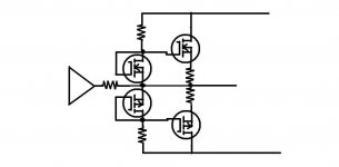
Is it possible to change the output FETs of the diagram below? i am thinking of IRF9540/540 please refer here.
Thanks,
Nat
Is it possible to change the output FETs of the diagram below? i am thinking of IRF9540/540 please refer here.
Thanks,
Nat
An externally hosted image should be here but it was not working when we last tested it.
IRF540 has a relatively high gate threshold voltage so you would want to change D3 and D4 to generate more voltage than the current 0.7V. You could try TL431s then you can program the voltage - trouble is that IRF540 has a threshold voltage tempco which means the hotter it gets the more current it draws. You will either need an oversized heatsink or some kind of thermal feedback.
Q2 IS upside down.
Without a cap in series with R1 you run the risk of DC from your source being amplified to higher DC to your speaker.
As abraxalito wrote, the D3 and D4 need to match the Vgs of Q1 & Q2 and track at temperature.
One way this can be done is to get another Q1 and Q2 as substitutes for D3 and D4 with their gates connected to the drains and mounted close to Q1 and Q2 on the heat sink.
Attachments
Last edited:
HexFETs (IRFP240/9240)
Hi Nat,
If I may ... ask a question
Why taking some schematic from the internet, plus trying to change the laterals to HexFETs without enough understanding of the key principles
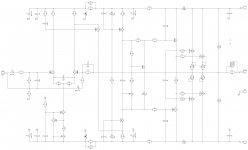
Why not taking something predominantly high-quality like this:
VHex amplifier
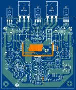
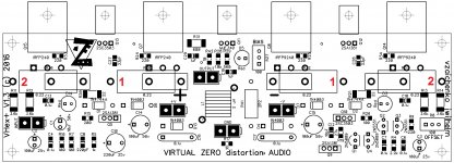
or a more its more powerful version (2 pairs of output devices):
VHex+ build photo
At least you can talk to the people who designed the thing and who will help you to make it working properly.
You can etch the PCBs yourself or buy the manufactured ones - all the options are avalable - up to the prefferred level of your involvement in the build process
See more details in the thread behind the links above and on the website in my signature.
Just as a recommendation
Cheers,
Valery
Hi Nat,
If I may ... ask a question
Why taking some schematic from the internet, plus trying to change the laterals to HexFETs without enough understanding of the key principles
Why not taking something predominantly high-quality like this:
VHex amplifier
or a more its more powerful version (2 pairs of output devices):
VHex+ build photo
At least you can talk to the people who designed the thing and who will help you to make it working properly.
You can etch the PCBs yourself or buy the manufactured ones - all the options are avalable - up to the prefferred level of your involvement in the build process
See more details in the thread behind the links above and on the website in my signature.
Just as a recommendation
Cheers,
Valery
Attachments
"f I may ... ask a question
Why taking some schematic from the internet, plus trying to change the laterals to HexFETs without enough understanding of the key principles "
He come here to ask a question and possibly learn.
OK, then let me elaborate a little bit.
NE5534 maximum output swing is 10V RMS at +/-18V rails. With HexFETs, biased at roughly 4V DC each, we loose additional 2.8V RMS, resulting in 7.2V RMS at the output, giving us 6.5W RMS as a maximum.
HexFETs need the bias spreader, providing appropriate thermal feedback for keeping the bias stable (lateral FETs don't require thermal feedback).
Input capacitance of HexFETs is higher and more non-linear, requiring lower output impedance of the driver stage - here NE5534 is powerful enough for driving one output pair, however distortion profile is unknown.
Compensation scheme needs to be checked.
So ... it's possible to make it working, but requires some effort.
Cheers,
Valery
I would be using a Vbe multiplier with the transistor on the heat sink.
The 2 diode drops are miles away from setting the right bias.
You probably need to be about 5-6 volts to turn on both mosfets.
A trick I use is to put a 6v8 zener across the multiplier so I don't accidentally fry the output mosfets.
The 2 diode drops are miles away from setting the right bias.
You probably need to be about 5-6 volts to turn on both mosfets.
A trick I use is to put a 6v8 zener across the multiplier so I don't accidentally fry the output mosfets.
Last edited:
hey val. is it possible to use lm317 to act as spreader? (just thinking out of the box)
please ignore the cost for the sake of this discussion..
Hi Nat,
Yes, in general lm317 can be used as a spreader with a couple of resistors and a trim pot, allowing the right idle current adjustment.
However, what will require additional testing - its tempco. One of the important functions of the spreader is to regulate the bias according to the output transistors' temperature - it's placed on the main heatsink, providing the thermal feedback. I have a tested configuration of TO-126 transistor with the red LED in series, providing the right tempco for keeping IRFP240/9240 under control. But I don't know the voltage vs temperature characteristic of lm317.
If you try and share the results - that would be useful.
Just be careful - start with low bias, then gradually increase it, until you have 80-100 mA of the output pair quiescent current (the output pair will become considerably warm at this stage). Then see if it will stay stable (lm317 is at the same heatsink with the output pair all the time).
Cheers,
Valery
- Status
- This old topic is closed. If you want to reopen this topic, contact a moderator using the "Report Post" button.
- Home
- Amplifiers
- Solid State
- IC + FET redesign