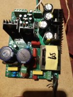
So I couldn't figure out why my amp sounded very bad until I finally saw the (short -120v) and (open-240v) selector connection holes on the board. I connected a jumper and then tested it, with amp disconnected because that made it easier to inspect with my multi-meter and I finally had my full voltages, 72v, not the 38v I had before. In my moment of joy I rushed and I forgot about the capacitors. When I connected the smps to the amp the connection arced loudly and with a blueish white color. The hbp500 smps had a blown mosfet, fuse, rectifier, and driver. I've ordered another smps because it'll be nearly a month to get most of the replacement parts that were blown and I can't find the driver part numbers on the power supply because they have obliterated the part#'s anyways. I cannot afford to pay another $40 for a third smps I really need to know if the amp could blow my new smps and how I can test it if it can. I do not have an oscilloscope yet only a multi-meter right now. Thanks in advance.
Attachments
I really don't understand the question. I have large experience repairing SMPS and with some ones designed for my own use. If the part numbers are erased and relabeled, only a certain amount of experience may give you an idea if they are common parts repainted or specifically designed for your own use.
There are myriads of SMPS controllers from the first I knew, the TDA4501 to modern ones like resonant and phase shiftted bridges. But several of them are very common and their topology easy to detect including the repainted units: TL494, UC384X, and the like. Some discrete SMPS around transistors or based upon LM555 also very rare in practice.
There are myriads of SMPS controllers from the first I knew, the TDA4501 to modern ones like resonant and phase shiftted bridges. But several of them are very common and their topology easy to detect including the repainted units: TL494, UC384X, and the like. Some discrete SMPS around transistors or based upon LM555 also very rare in practice.
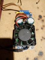
I'm trying to figure out how to test the irs2092 amp board components before I connect a new smps to it. I do not want to blow another one as it isn't cheap plus it takes a while for delivery.
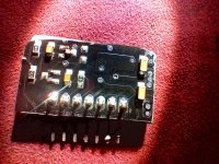
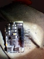
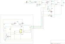
Here are photos of the ic I doubt it'll help.
Here are photos of the ic I doubt it'll help.
Attachments
Last edited:
Connect your amp to new SMPS adding a 12V 65W or so car lamp in series with each 72V rail.
NO speaker or any other load.
If all normal, lamps will blink and practically become invisible, I would expect dull red or dark orange at most once it stabilizes (a couple seconds).
If amp is shorted, lamps will blow like fuses, protecting the SMPS
NO speaker or any other load.
If all normal, lamps will blink and practically become invisible, I would expect dull red or dark orange at most once it stabilizes (a couple seconds).
If amp is shorted, lamps will blow like fuses, protecting the SMPS
I have the same smps, and it had blown out without any load. I just wanted to check the voltage before I connect the amp board. The second smps board is ok, but it produce ±75V dc. (It should be ±65, but I have 245V ac with solar panels on my rooftop.) So I think ±75V is too much for the amp. Is there anybody who knows how can I correct the output dc voltages by replacing some parts? Thank you in advance! 😄
Attachments
- Home
- Amplifiers
- Class D
- I stupidly connected my 65v, 500w HBP SMPS to my IRS2092 amplifier board without draining the capacitors and blew my SMPS the amp ok for new SMPS?