Help me to understand the application notes for Texas TPA 3123 amp.
The pin out has Gain 0 and gain 1 .
How to use this to set a gain of about 26 db ?
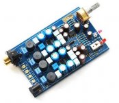
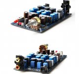
I have a muse TPA 3123 build up board with too much gain. It is a BTL with an op amp has phase splitter.
thanks
kp93300
The pin out has Gain 0 and gain 1 .
How to use this to set a gain of about 26 db ?
I have a muse TPA 3123 build up board with too much gain. It is a BTL with an op amp has phase splitter.
thanks
kp93300
Attachments
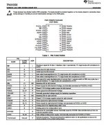
Pull GAIN0 low, ie connect it to AGND
Pull GAIN1 high, ie connect it to AVCC through a for example 100KOhm resistor.
Pull GAIN1 high, ie connect it to AVCC through a for example 100KOhm resistor.
Hi saturnus
this is most helpful!!
I need a bit more hand holding.
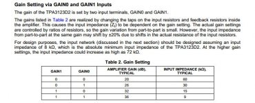
In table 2 gain setting table, the value 0 means connect to AGND and value 1 means connect to AVCC via a 100K resistor? Is the value of this resistor critical ?
there will be 2 resistor to change if i am interested in 26 db gain ??
much appreciated
kp93300
this is most helpful!!
I need a bit more hand holding.
In table 2 gain setting table, the value 0 means connect to AGND and value 1 means connect to AVCC via a 100K resistor? Is the value of this resistor critical ?
there will be 2 resistor to change if i am interested in 26 db gain ??
much appreciated
kp93300
That's 3 questions in one sentence.
Logic 0 means less than 0.8V and less than 1µA. Connecting to AGND will achieve that.
Logic 1 means more than 2V and less than 125µA. Connecting to AVCC will achieve the voltage part of the requirement. As for the current part you'll have to calculate it by using Ohm's Law (U/I=R) so the value of the resistor should be between 80K and 240K ohm depending on your intended supply voltage.
Don't know the set up now so I don't know if there's 2 resistors that needs changing.
Hi saturnus
thanks . i understood.
i check the board and found that the AVc pins are tied to Gain 0 and Gain1 and no resistor in sight.!!
I hope to find another board to do surgery .
despite this, it sounds very very good in my Markaudio 12 p single way driver..
The realism is spooky for a board that is less than US 20 !!!! it even rocks with Kitaro music .
Thanks once again
much appreciated
regards
kp93300
- Status
- Not open for further replies.
- Home
- Amplifiers
- Class D
- How to set gain of TPA 3123 chip ?