Hi,
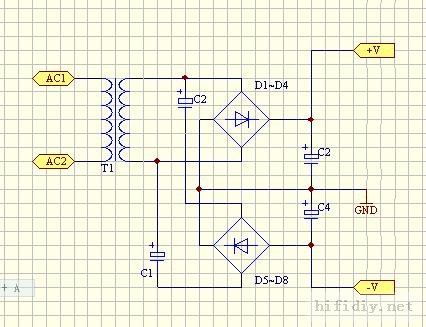
Try typing 'rail splitter' your search engine and see what it brings you. C1+C2 are not needed in your design, C3 + C4 need to be chosen to have a working DC voltage greater than the voltage on either rail and to have sufficient charge holding capacity (depends on what you finally intend using the supply for).
Also you have parallelled the two bridge rectifiers together so if you want to have two dual supplies then this design will not do, you need to seperate the two rectifiers then tap two live/neutral cables from the transformer. One cables live/neutral will go to the '~ ~' symbols on the one rectifier and then your circuit '+ -' will come from the '+ -' on the rectifier. Then you do the same with the other rectifier (I hope you are following me). Next you put in your reservoir capacitors (c3 + c4 in your drawing) and the centre point of these is your circuit ground and the top of one capacitor is positive and the bottom of the other is negative.
You could then add bleeder resistors across the reservoir caps (if it is to be of high current/voltage) and even some form of regulation if you need/want it, and also some bypass caps for the main reservoirs to aid charging and discharging.
I hope this helps (and doesn't confuse)
Thanks
Gareth
Thanks for the reply. I think C1 and C2 is necessary, otherwise the diodes in two bridges essentially short the transformer. Even this design (I got it from some forum) I still have doubts. Most common design I see working is the half-wave rail split, which is similar to the voltage doubler. But are there any way to achieve full-wave rectifier without center tap in transformer second winding?
You can make an inverting switching regulator, see part LT1071CT
http://www.linear.com/pc/downloadDocument.do?navId=H0,C1,C1003,C1042,C1031,C1061,P1266,D2406
http://www.linear.com/pc/downloadDocument.do?navId=H0,C1,C1003,C1042,C1031,C1061,P1266,D2406
You could make two half waves rectifiers.
Ground one end of the seconday, and the other end goes to the cathode of a diode for the negative supply, and the anode of a diode for the positive supply. You need much more filtering capacitance though. Only two diodes instead of two whole bridges.
Ground one end of the seconday, and the other end goes to the cathode of a diode for the negative supply, and the anode of a diode for the positive supply. You need much more filtering capacitance though. Only two diodes instead of two whole bridges.
Yea, a voltage doubler. Only thing is that your transformer voltage has to be lower than (1/2) of what your max voltage is.
In your application, One AC leg of the transformer and GND is at the center connection of the caps, and you get your split voltages from the two caps, no resistor dividers needed.
An externally hosted image should be here but it was not working when we last tested it.
In your application, One AC leg of the transformer and GND is at the center connection of the caps, and you get your split voltages from the two caps, no resistor dividers needed.
eboy2003:
The jumper in the drawing supplied by EWorkshop1708 must be installed unless the load current on each supply is identical. Ignore the 120/220V note.
If you ground the center of the two capacitors, then the output voltage will be equal to the winding voltage like a standard bridge design. i.e. a 12VAC winding will produce about + and - 17VDC minus the 2 times the diode drop (12VAC RMS times 1.414 = 16.9VDC - .6 - .6 = or +/-15.7VDC). EWorkshop1708 is referring to the peak to peak positive and negative when he says the output will be twice the transformer rating
Remember the diodes must be rated at least 2 X output voltage.
you can go for virtual ground but use power opamp like opa549(check again if it is unity gain stable or not) instead of the tiny ones
or if you are building a chip amp, say lm1875, you can use another 1875 as a virtual ground")
or, go for a discrete virtual ground like Sijose did.
or if you are building a chip amp, say lm1875, you can use another 1875 as a virtual ground
or, go for a discrete virtual ground like Sijose did.
eboy2003 said:Thanks all for reply. If the transformer has center tap, the ground line is actually connected from the center tap to the center of the two caps. I'm wondering what is the difference to connect center of the two caps to the AC line or center tap?
Hi,
Do you mean the primary when you say AC line ? And the secondary for the centre-tap ?
Thanks
Gareth
eboy2003 said:I have a good r-core transform with single output of 36V without center tap. What is the best way to split the rail to create regulated +/- 12-15V DC for at least 1A? [/B]
The best way is to use a different transformer. 36VAC will give you about 50V DC after the rectifier. You could of course set up a virtual ground, but you'd still have +- 25V where you want +-15 max regulated, so you'd convert 20V * Iout into heat at least.
The simple way to get +- without center tap or virtual ground, using two half-wave rectifiers (i.e. 2 single diodes) in this case would get you some +-50V = 100V total, far too much.
A stock 15-0-15VAC transformer + rectifier + caps will get you +-21V DC, just fine for +-15 regulated.
If this were an unmodifiable specification where you'd have to mke do with the 36VAC or 50VDC input (like in telecommunications equipment), a switching regulator could turn the +50 into +-15 VDC easily - a basic step-down converter with a second winding on the inductor for the negative output, perhaps.
- Status
- This old topic is closed. If you want to reopen this topic, contact a moderator using the "Report Post" button.
- Home
- Amplifiers
- Power Supplies
- How to create +/- DC from a single transformer output without center tap?