")
What type of help do you need exactly? You just pick a type of hexfred that fits the application (what is the ac voltage to be rectified and at what current?) and put it in the circuit (do you need help how to wire it up?).
Voltage drop across the hexfreds will be lower than across the 866, so you will have to either add dropping resistors (calculate value by current draw) or if the load are tubes change bias to where it needs to be.
Sorry if I sounded like a dick, it wasn't my intention. A bit more information is needed to guide you through that change.
Hi schiirrn,
Thanks for the reply. A few follow up questions:
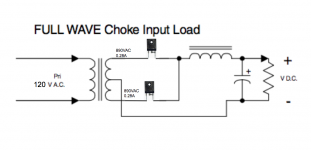
The hammond transformer rectifier guide says to select rectifiers that are 0.45 * VAC. In this case, the secondary is 1780VAC center tap (890VAC per leg). Should the rectifier be sized for 0.45 * 1780 or should it be 0.45 * 890?
Notice the attached diagram. Is the rectifier anode and cathode wired correctly? The anode is connected to the secondary while the cathode is connected to the choke. Is this correct?
Finally, will the hexfreds generate heat and if so, do they need to be mounted on a heat sink?
thanks!
Thanks for the reply. A few follow up questions:
The hammond transformer rectifier guide says to select rectifiers that are 0.45 * VAC. In this case, the secondary is 1780VAC center tap (890VAC per leg). Should the rectifier be sized for 0.45 * 1780 or should it be 0.45 * 890?
Notice the attached diagram. Is the rectifier anode and cathode wired correctly? The anode is connected to the secondary while the cathode is connected to the choke. Is this correct?
Finally, will the hexfreds generate heat and if so, do they need to be mounted on a heat sink?
thanks!
Attachments
tubesoiliron, if you don't provide any detail on why you want to make the change, and the power supply and amp you are making the change on, and the amp's operating conditions, then others won't know if any advise is good advise or bad advise, or have a clear picture of why you are choosing a particular design path.
Type 866 were always operated into a choke input, so you'll want to prepare for its inductive peak voltages under all conditions. Modern rectifiers won't safely handle big voltage transients without using several in a series string, each having a voltage equalizing (for the reverse voltage condition) resistor across it. Resistors also have a voltage rating, so you'll want to study up on that, and on some high voltage capable insulating mounting.
Old amateur radio ARRL handbooks are a great source of information about this - 1960s era maybe. And a schematic of what you're working with is essential for any real advice.
All good fortune,
Chris
Old amateur radio ARRL handbooks are a great source of information about this - 1960s era maybe. And a schematic of what you're working with is essential for any real advice.
All good fortune,
Chris
Here is a free program but it will take a little work to understand it. But as Chris just pointed out you may need a very high voltage rectifier. I just played with it but without a lot more data than you have like the resistance of the transformer, what size choke you are using and so forth it can't give exact reports. But one down and dirty simulation hinted that you may need a pair rectifiers rated at over 5,000 V.
PSUD2
PSUD2
890VAC rectifier choke, you need twice the peak voltage, so 2,516V PIV.
(The "Hammond chart" is wrong in several places.)
The wise designer adds LOTs of overhead to this to cover line-spikes and the unexpected.
The highest rated HEXFREDs I found in a quick search are 1,200V PIV. So even two in series may not do. (I'll grant the 16V over but I do not know if HEXFREDs in series will share voltage nicely; some series-strings the weakest link fails first and then the others burn.)
Attachments
I guess Fahey is right, if you have all the parts for maintain the 866, why you complicate your life changing them?
The voltage expectancy will not change much more as 0.9XACvoltage but the peaks you will have with choke input filter, needs many in series diode with resistor and capacitors in parallel.
The voltage expectancy will not change much more as 0.9XACvoltage but the peaks you will have with choke input filter, needs many in series diode with resistor and capacitors in parallel.
My intent was to move away from the mercury tube rectifiers (and all that goes with it) and go toward a more compact, simple hexfred design. In my simple mind, I was hoping for a simple solution but it sounds like I am off base here. I will likely still with the 866a tubes for now.
Perhaps you may get more directly applicable advise if you link to the actual circuitry you have for the power supply and amp. Without the actual details, it is possible to misinterpret the few details you have provided and make incorrect assumptions. You also don't indicate if you can confidently make changes to circuitry and make measurements to support those changes.
You may just need some UF4007's.
You may just need some UF4007's.
how about microwave diodes......
or.. Univerzalne diody THT: Max. zaverne napatie: 2.2kV, 4kV, 6kV, 8kV, 12kV, 4000V | Prud v priepustnom smere: 0.5A, 1A, 30A, 500mA, 3A, 25A
or.. Univerzalne diody THT: Max. zaverne napatie: 2.2kV, 4kV, 6kV, 8kV, 12kV, 4000V | Prud v priepustnom smere: 0.5A, 1A, 30A, 500mA, 3A, 25A
I would suggest 3 to 4 serial connected BYW96 or equivalent.
Those are cheap,fast, soft recovery 1000V 1A avalanche diodes that wont require high voltage resistors in parallel.
Why I suggest those?
I used them to replace 3-phase bridge mercury rectifiers feeding transmitter tubes with up to 6kV/1A.
There where occasionally flashovers (mostly do to mishandling by the operator).
The diodes where only protected by a electromechanical overcurrent trip.
At occasional inspections I could find some of the diodes shorted, but the rest took up the burden and functioned as ever.
When using "normal" diodes with paralled resistors (with and without additional snubbers) all diodes in at least 2 strings usually died after a serious flash over.
I have no expirience with more recent avalanche diodes but since there avalanche characteristics seem not to be worth to be specified I would stick with the good old BYW96.
I have a few of these:
Antique Radio Forums • View topic - FS Solid state 866A tubes
Not sure how they would perform in audio equipment though.
Antique Radio Forums • View topic - FS Solid state 866A tubes
Not sure how they would perform in audio equipment though.
Then there's …
Mfr. Part № - Vishay RGP02-20×10⁻E3/53
50¢/ea qty 1, 37¢/ea qty 100.
2 kV, 0.5 amp, 1.8 VF at ratings.
I've used them … solid as rocks.
At the price listed, you could also pair them up, use 4 of them for the circuit shown above. 2 on each leg, with a 2.2 MΩ resistor in parallel, to each one. Back current is 0.314 mA, peak. Each rectifier max reverse VR is about 1,400 V. Easily within specification limits. But if you're still worried about the choke-input do-wah down-wind and its reverse flyback EMF, well .. put 3 in a string on each leg, with 3 ea., 2.2 MΩ resistors in parallel.
The resistors need only be 1 watt devices.
Anyway.
Just a couple o thoughts.
-= GoatGuy ✓ =-
- Status
- This old topic is closed. If you want to reopen this topic, contact a moderator using the "Report Post" button.
- Home
- Amplifiers
- Tubes / Valves
- Hexfred rectifier instead of 866A tubes