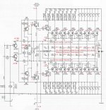
I'm having rather a lot of trouble getting the transistor output stage of a hybrid power amplifier I have working. I have included a snapshot of the output stage.
The output transistors are turned on to the point that even with very low rail voltages they conduct enough current to open the power supply protection. I can get up to about 5V (+2.5 / -2.5 VDC) on the rails and make some measurements in the circuit.
As rail voltage increases, the voltage on the output transistors' bases maintains a level at which the output transistors pass more and more current.
By using a resistor to bleed some voltage from one or the other rail onto the base of Q12, Q10, and to some extent Q8, the associated output transistors can be turned more on or more off. This leads me to think output transistors are good as well as Q12, Q10, and maybe Q8. I did replace Q5 and Q6 which had no effect.
At 5VDC between the rails, voltages are mirrored between halves of the circuit. Voltage measurements are below:
At Q14 base: -0.63V
At Q12 base: -1.28V
At Q10 base: -1.90V (the right side of R30)
At Q10 base: -1.26V
At Q6 emitter: -0.57 (stays there, to whatever voltage amp powered to; according to the schematic is should be the opposite sign with +0.55V)
I also replaced Q7, which was a DN2530 and did not appear to ever have been changed. The schematic doesn't seem to say what Q7 should be. Changing it had no effect.
What would you do next? Assistance is much appreciated. Please let me know if more information is needed. Thank you!
Attachments

> according to the schematic is should be the opposite sign with +0.55V)
Schematic is mixed-up there. Both bases are the same and very near zero V. Then the upper emitter (Q5) has to be more-positive than zero V, and vice versa for the lower (Q6).
Q7 and R36 are *critical*. They should not need replacement. They should be checked for bad joints. While most bad joints will just shut-down the whole output, a floating gate (or different pin-out!) could drive it crazy.
I don't see how this was *ever* biased happy. We want something near six diode-drops between Q11 base and Q10 base. The plan as drawn (with obvious draw-overs) shows the one diode in each NJL3281 plus an unknown current in 43r, twice in parallel. Taking any reasonable guess for Q9 Q8 current we get <=1V bias *total*, where we want just over 3V, so "it should run cold". You say it burns-up.
You could TRY four 1N4007 diodes in series, pointed down, across C6. That would limit the bias to ~~2.4V and it should run cold, and "hoarse" at small output (crossover distortion). But that's at-best a check on what ELSE may be wrong.
Indeed, Q7 and R36 are a current source, mirrored through Q8-Q9 into the circuit. As said by PRR, very critical!R36 should set the bias, increase value to reduce output stage bias current.
My guess is a current of 1 mA through Q7-R31-R32 to start with, yielding in a load of 4 mA (max) for Q5-Q6. If something is wrong with Q7, you might have an increase of this biascurrent when increasing the rails, where a independend current was expected (what you experience).
Replace Q7-R35-R36 combo for a regular series pot and fixed resistor.
Voltage across this PR is 2*64=128V, current say 1mA.
Resistor 100k/1W and pot 47k/1W.
You should be able to increase rails to 'normal values' with the pot at max value. Be carefull with setting bias!
PRR, you are right that there is more to the temperature bias circuit. I accidentally cut off a note that there are six pairs of output transistors, so there are the six diodes you note. Also, R44 is not a resistor but a diode. This circuit has continuity and seems in order.
I tried some resistors in parallel with R36. The bias changes but the output still runs away by 30VAC at the power transformer even down to the tens of ohms across R36. I also tried some resistors across Q7-R35-R36 with the same result.
The circuit seems responsive- the bias changes with adjustment to R36- but it is not producing a voltage at Q14 and Q15 that is very close to right.
The amplifier did not appear to have been modified at all when I got it, so presumably the original circuit worked. It seems there is something significant I am missing. I would change more 2SA1837 and 2SC4793's, but voltages are mirrored and the circuit seems responsive.
What should I do next? I very much appreciate the help.
Last edited:
...there are the six diodes you note.....
Then you have a broken wire (much less likely: bad diode).
The outputs remain under control with a 10-ohm resistor in the place of R36. At about 30VAC input the 1/4-watt ratings of R34 and R33 are exceeded and the amplifier can't be powered the rest of the way up.
So I am wondering, how does this circuit respond to less than full voltage? This amplifier has a soft-start circuit that places a 10-ohm resistor in the AC line and then closes a relay across it after a short period of time. Can it be expected that this circuit will control bias at ~120VAC input, but not at 20VAC input?
If so, that would explain why my testing at low voltage does not produce successful results. I am afraid to attempt a full voltage power-up, since if there remains something wrong it could destroy the matched output transistors. After all this, I still haven't found anything wrong. When I got it, it pulled too much current across the 10-ohm soft start resistor and didn't make it through start-up.
Thank you for your assistance!
Measuring the voltage between the the Q10 and Q11 bases is interesting. With R36 adjusted so output transistors conduct the same, measured at each 0.2-ohm resistor, the below are the results:
3.74V Q10-Q11 bases, 5mV each 0.2-ohm resistor, 5.29V between the rails
3.79V Q10-Q11 bases, 10mV each 0.2-ohm resistor, 5.42V between the rails
3.62V Q10-Q11 bases, 15mV each 0.2-ohm resistor, 5.54V between the rails
3.66V Q10-Q11 bases, 20mV each 0.2-ohm resistor, 5.6V between the rails, 20mV is specified bias
3.50V Q10-Q11 bases, 25mV each 0.2-ohm resistor, 5.69V between the rails
3.51V Q10-Q11 bases, 30mV each 0.2-ohm resistor, 5.73V between the rails
3.55V Q10-Q11 bases, 37mV each 0.2-ohm resistor, 5.60V between the rails
It appears the power supply is getting pulled down at 37mV at each of 24 total output transistors. For a couple hundred watt per channel amplifier, is that right?
What does this information tell us? What further tests would be useful?
The bias circuit is not logical.
Current through Q5-Q6 is 1.1mA. Voltage over R43-diodeNJL is 3.3 in total according to drawing (should be ok for normal bias setting).
However, current through R43-diode calculates (3.3-0.7) / 43.2 = 60mA ???
Same value for R44-diodeNJL1302, summing to 120mA out from Q9 into Q8 ???
If R44 is a diode, it makes no sense at all.
No specs in datasheet about the diode in the NJL, single presumed.
Do you have a full circuit drawing available?
R44 and R43 are SB120 Schottky barrier rectifier diodes.
The datasheet for the NJL shows one diode.
With respect to the output stage, there are some capacitors, inductors, and resistors between the rails and ground; and there are six pairs of NJL output devices. The tube stage is separated from the output stage by a 4.0uF capacitor (shown) in parallel with a 0.0024uF capacitor (not shown). The bases of Q5 and Q6 are held directly to ground in mute mode. The diodes in the NJL's are connected in series. I don't believe there's anything else not shown. Is there something of particular interest?
I think I'm going to take some time to calculate currents and voltages around the circuit and see if I can understand what must have been going on when the circuit was functioning.
If I want to replace the bias and associated circuit with something that will work well, where would you suggest looking?
Thank you all very much.
Very curious, as the drawing shows two resistors instead! Did you exchanged the shown resistors for Schottky's, and if so, why? Are the values of the shown resistors 43.2E, or can it be 432E or something like 43Z? (a 4.3V zener would protect the endstages from overbias)R44 and R43 are SB120 Schottky barrier rectifier diodes.
Both Schottky's and 43.2E resistors make no sense here.
I noticed in #13.The datasheet for the NJL shows one diode.
Fine.With respect to the output stage, there are some capacitors, inductors, and resistors between the rails and ground; and there are six pairs of NJL output devices.
FineThe tube stage is separated from the output stage by a 4.0uF capacitor (shown) in parallel with a 0.0024uF capacitor (not shown).
FineThe bases of Q5 and Q6 are held directly to ground in mute mode.
Full circuit drawing, above in #13. Send by pm if neccessary.The diodes in the NJL's are connected in series. I don't believe there's anything else not shown. Is there something of particular interest?
Fine, use the full circuit drawing to incorporate all.I think I'm going to take some time to calculate currents and voltages around the circuit and see if I can understand what must have been going on when the circuit was functioning.
Post #4, second part.If I want to replace the bias and associated circuit with something that will work well, where would you suggest looking?
You're welcome, happy to help.
I am reasonably confident the SB120's came from the factory. This amplifier shows no signs of ever having had any work done on it. To change out the SB120 diodes the output boards would have to be separated from the heat sinks either by removing the transistors from the heat sinks or by unsoldering them. Everything looks too clean for that ever to have been done.
That does not, of course, explain how this was actually working.
I'll PM the full schematic and you can tell me if I have completely missed something important.
I very much appreciate the help.
That does not, of course, explain how this was actually working.
I'll PM the full schematic and you can tell me if I have completely missed something important.
I very much appreciate the help.
The end stage consists of six parallel PNP's to the neg-rail and ditto NPN's to the pos-.
The build in diodes in these bjt's however are in series and in series with the 43.2 ohm resistor. This yields to a nominal bias of 3.3V, adjustable with trimmer R36. (Current through both legs are some 7mA, which is a nice value.)
If the rails keep low, one or more of the output-bjt's are conducting magma instead of proper transistors.
I posted a lenghtier pm to Unimog.
I have done some more work on this amplifier and have included some more information here. I have taken the below steps:
1. Replaced the diodes previously at R43/R44 with resistors. This had no affect on the problem.
2. Recorded the voltages around the circuit and attached them to this post. The behavior of all the output transistors appears normal to me. Am I missing something? Voltages at the integrated diodes in the output devices are included.
3. Measured voltage at the output transistor base with respect to ground and voltage across output transistor current sense resistors. Results are below:
Voltage at output transistor base with respect to ground / Voltage across 0.2-ohm resistor
0.548VDC / 0.001VDC
0.586 / 0.005
0.603 / 0.010
0.615 / 0.015
0.628 / 0.020
0.639 / 0.025
0.644 / 0.030
0.661 / 0.040
Overall, the circuit appears to me to not be successfully regulating the voltage at the output transistors' base as rail voltage is increased. The voltage at the output transistors' base increases as rail voltage increases and the current conducted by the output transistors appears to increase accordingly.
Any help given this information would be much appreciated. Please let me know if any additional information or testing would be helpful. Thank you all very much.
Attachments
- Status
- This old topic is closed. If you want to reopen this topic, contact a moderator using the "Report Post" button.
- Home
- Amplifiers
- Solid State
- Help with transistor amplifier output stage?