I've just completed building Elektor's compact High End Amp as featured in the March 2005 edition as the last piece in my office compact hifi (preamp and DAC from Elektor are up and running).
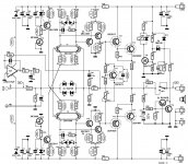
I fired it up on the weekend, ran through all the checks, set the bias current, fired up the sign wave generator and oscilloscope to check it under load. All seemed to be working ok, except it seemed to be clipping at about 8V output rather than in excess of 20V that it is supposed to (give or take, the supply rails are +/-25V). I went and checked all the voltages in the circuit and noticed in both channels the voltage drop across R13 and R15 is only about 2.4-2.7V rather than the 5.5V specified. In the accompanying text, Ton says
"As can clearly be seen, all of the operating points in the amplifier are directly dependent on these two current sources, so we gave particular attention to their design. The reference voltages for the current sources are provided by flat LEDs, which in turn are operated at reasonably constant currents provided by a pair of simple JFET current sources. As a result, the current sources built around T3 and T4 are practically immune to power-supply ripple and supply voltage fluctuations. Unfortunately, JFETs have a rather large tolerance range, so you should measure the voltages at the points shown on the schematic diagram and compare them with the indicated values. A deviation of more than
20% is not acceptable."
So I swapped out the two BF245A to see if it made any difference (same brand, but different batch), but the values were about the same. I've order some Fairchild ones to see if it changes.
My question is, would this be responsible for the amp clipping at the level it is? And failing being able to get other BF245As to give a better result, could I drop R13/R15 to 470R, so the voltage drop/current is as per specified?
Or does anyone have other suggestions as to why I would be getting this result?
Schematic attached
Attachments
Yes this can be easily the cause to the clipping artifact!
To try this out you can simply short the BF245A-s or rather put there a
10k trimmer and adjust (starting from the 10k value) until there is the desired 5.5V on the 1k resistor.
If this is already working without clipping we can go further replace the BF245As with something else...")
To try this out you can simply short the BF245A-s or rather put there a
10k trimmer and adjust (starting from the 10k value) until there is the desired 5.5V on the 1k resistor.
If this is already working without clipping we can go further replace the BF245As with something else...
Yeah in the meantime I am working on the BF245A issue.
As I saw on the datasheet it has a diversity (or how do you say the range of
values guaranteed by the manufacturer?!) in the drain current from 2 to 6.5mA.
BTW: in a lot of design there is only a simple resistor in this place.
As I saw on the datasheet it has a diversity (or how do you say the range of
values guaranteed by the manufacturer?!) in the drain current from 2 to 6.5mA.
BTW: in a lot of design there is only a simple resistor in this place.
As it's shown in the datasheet BF245B has already some greater currents
so you already could try them with this adjustable layout discussed here:
http://www.diyaudio.com/forums/part...tiometer-variable-constant-current-diode.html
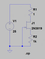
Or any other jFET which handles at least 25V (VDS) and the
IDSS > 5.5mA + 1k trimmer between G and S.
As I simulated with 2n3819 (having ID = ~12mA when GS was shorted)
with a layout like this you can adjust the current starting from ~1.8mA.
5.5mA was achieved with R2 = 180R.
so you already could try them with this adjustable layout discussed here:
http://www.diyaudio.com/forums/part...tiometer-variable-constant-current-diode.html
Or any other jFET which handles at least 25V (VDS) and the
IDSS > 5.5mA + 1k trimmer between G and S.
As I simulated with 2n3819 (having ID = ~12mA when GS was shorted)
with a layout like this you can adjust the current starting from ~1.8mA.
5.5mA was achieved with R2 = 180R.
Attachments
Last edited:
- Status
- This old topic is closed. If you want to reopen this topic, contact a moderator using the "Report Post" button.