I just bought a second hand scope on eBay which was sold as faulty because the people selling didn't know how to test it, but they said they could get a line to come up if they twiddled some knobs.
When it arrived I plugged it in and had a play with it. The problem I have is that with the Y-Pos at it's lowest position on both Ch1 and Ch2, the trace is right at the top of the screen. Shown here:

The scope is a Hameg HM512. I have found a German manual for this scope and took the back off the scope to see if I could adjust the Y position. I found a pot that did just this, but it only took the traces down 30mm and the voltage on the CRT tube pins that should read 42V went down to 0V, so I think this is not the problem.
I notice that there is an LED on which says Overdrive, does anyone know what that is, maybe this is something to do with my problem.
Any help would be great.
Thanks in advance
Craig
When it arrived I plugged it in and had a play with it. The problem I have is that with the Y-Pos at it's lowest position on both Ch1 and Ch2, the trace is right at the top of the screen. Shown here:
The scope is a Hameg HM512. I have found a German manual for this scope and took the back off the scope to see if I could adjust the Y position. I found a pot that did just this, but it only took the traces down 30mm and the voltage on the CRT tube pins that should read 42V went down to 0V, so I think this is not the problem.
I notice that there is an LED on which says Overdrive, does anyone know what that is, maybe this is something to do with my problem.
Any help would be great.
Thanks in advance
Craig
Open it up and look for leaky, corroded or bulging capacitors, especially in the power supply. I'm not familiar with this specific model, but faulty capacitors is a common problem in older scopes. In the manual, look for a listing of voltage references and test them. Also check ripple voltage on those references.
Thanks for the reply Lukky.
I just downloaded a manual, in English, for a different model than the one I have, and it says:
[This indicator shows any vertical overscan of the usable (10x8) screen area, if any part of the signal or baseline are outside the graticule. The indicator is achieved by 2 LEDs. Should one LED illuminate without an inpout signal, this means that the respective vertical positioning control has been improperly adjusted.]
I am assuming Overscan and Overdrive are the same thing here!
There are 2 pins on the back of the CRT which D3 and D4 and according to the manual they are Y-Plate +42V. When I adjust the Y-Plate pot, one of them changes and the other stays at 74V!!! Could this be the problem? and if so, how do I even start about sorting it?
Thanks
If I set the Ypos dial on Ch1 and Ch2 to midway and then adjust the Ypos pot in the rear of the machine to get 42V on the D4 pin, I can then get the traces a sqaure and a half furhter down the screen whn I put the Ypos dials back down to zero. The D3 pin stays at about 70-74V all the time and the 'Overdrive' LED is still on.
I put 30V on the input and selected Invert mode and the trace hardly moved, even when selecting 2V/cm, could the inputs be causing the problem?
I put 30V on the input and selected Invert mode and the trace hardly moved, even when selecting 2V/cm, could the inputs be causing the problem?
Last edited:
The trace is not filling the screen on the X axis too.
If the EHT (and these faults could all be related) is too high then the CRT deflection sensitivity increases (harder to deflect the beam). Maybe it has all been twiddled internally.
I would check all the basics first. Check all the rails as a matter of course. If that shows nothing amiss then fault find just the Y position fault. The plates of the CRT are driven off what will be essentially a differential amp. As long as the voltage is equal on both Y plates then the trace should be centred so look for an imbalance in the output stage.
I checked the rails of the device. They are all within 5-10% of what the manual states.
I just checked the circuit diagram 'Y-Input, Attenuator and Y-Preamplifier' and I have to admit, it looks pretty complicated to me.
It seems strange why both inputs are way up the screen and the overrange LED is on. Surely both Y-input pre-amp circuits couldn't both be faults, could they?
I just checked the circuit diagram 'Y-Input, Attenuator and Y-Preamplifier' and I have to admit, it looks pretty complicated to me.
It seems strange why both inputs are way up the screen and the overrange LED is on. Surely both Y-input pre-amp circuits couldn't both be faults, could they?
All the gain stages are DC coupled. Any problem with the power supplies or bias will most likely cause both channels to behave the same. You mentioned a problem with the horizontal as well. With the input shorted the out put differential stage should be balanced. Work backwards. Observing the DCvoltages at each stage.
I didn't mention the H pos, Mooly did. I see what he means, in the picture I posted, the trace seems to be short at both ends, not really sure why it looks like that as it doesn't look like it now!
Can you explain a bit more please multisync.
I have the unit apart and I have been measuring the voltages at various parts of each board, and all seems correct with the drawings.
Can you explain a bit more please multisync.
I have the unit apart and I have been measuring the voltages at various parts of each board, and all seems correct with the drawings.
Here is what appears to be the proper print to your scope,
http://www.ko4bb.com/Manuals/11)_Stuff_Not_Sorted/4_Miscelaneous/OSCILLOSCOPE/HAMEG/HM512-6.pdf
It is basically two DC coupled amplifiers that are identical that were the inputs are out of phase.
The input stage is a Differential stage made up by two Jfet's (TIS69).
See page 19 of the document.
This is were you should start measuring voltages and compare them between the two haves.
Pretty straight forward as there is no Negative feedback or anything.
As you go along through each successive stage you should run into the one that it way would be the one to start looking for bad components.
It is very possible that one of the Jfet's on the input are bad due to an over voltaged condition at the input.
Also make sure that The input switch is working properly as well as on my scope (hitachi V-425) I get similar condition when it is not working right (terminating properly) and glitchy, Although this doesn't effect the position adjust.
What does an ac signal input to the scope look like?
This may not give any indication but it might help to Know if it is clipped on one of the halves of the waveform as both halves are identical DC coulped class A amplifiers.
Page 20 is the continuance of the stages all with a 12v supply.
At this point the output voltages should be the same as well, if they are not then the problem is in or before this stage.
The diodes are for switching the outputs of the two preamp stages on and off to the input of the final stage.
Notice that the Y position control is in the last stage before the Final amplifier as well.
The trigg signal Gen amp doesn't have anything to do with the main signal path and just creates a trigger pulse for the sweep system.
The invert switch, switches the two signals that are out of phase and the input signal from the preamp stage is common to the input to the trigger amp and the goes from there through the phase changing switch to the vertical position amplifier and then on to the final stage.
I hope this helps.
jer")
http://www.ko4bb.com/Manuals/11)_Stuff_Not_Sorted/4_Miscelaneous/OSCILLOSCOPE/HAMEG/HM512-6.pdf
It is basically two DC coupled amplifiers that are identical that were the inputs are out of phase.
The input stage is a Differential stage made up by two Jfet's (TIS69).
See page 19 of the document.
This is were you should start measuring voltages and compare them between the two haves.
Pretty straight forward as there is no Negative feedback or anything.
As you go along through each successive stage you should run into the one that it way would be the one to start looking for bad components.
It is very possible that one of the Jfet's on the input are bad due to an over voltaged condition at the input.
Also make sure that The input switch is working properly as well as on my scope (hitachi V-425) I get similar condition when it is not working right (terminating properly) and glitchy, Although this doesn't effect the position adjust.
What does an ac signal input to the scope look like?
This may not give any indication but it might help to Know if it is clipped on one of the halves of the waveform as both halves are identical DC coulped class A amplifiers.
Page 20 is the continuance of the stages all with a 12v supply.
At this point the output voltages should be the same as well, if they are not then the problem is in or before this stage.
The diodes are for switching the outputs of the two preamp stages on and off to the input of the final stage.
Notice that the Y position control is in the last stage before the Final amplifier as well.
The trigg signal Gen amp doesn't have anything to do with the main signal path and just creates a trigger pulse for the sweep system.
The invert switch, switches the two signals that are out of phase and the input signal from the preamp stage is common to the input to the trigger amp and the goes from there through the phase changing switch to the vertical position amplifier and then on to the final stage.
I hope this helps.
jer
I may have post the wrong link as the one I posted didn't have the LEDS on the front panel.
This one does and refer Fig 14&16 for the Y stage preamps and final amplifier stages.
KO4BB's Manuals
Sorry for the confusion !!
They are both very similar to one another with only a few changes but basically work the same as I had described.
jer
This one does and refer Fig 14&16 for the Y stage preamps and final amplifier stages.
KO4BB's Manuals
Sorry for the confusion !!
They are both very similar to one another with only a few changes but basically work the same as I had described.
jer
As a service engineer I repaired many oscilloscopes in the past. This is a typical problem, somewhere in the Y amplifier. The Y amplifier is fully symmetrical and DC coupled from the input. You should follow the back-to-front troubleshooting procedure. That means set the inputs to GND. Then using a piece of test wire, short the collectors of the Y amplifier last stage. Never the bases or the emitters. Don't be afraid, it will not blow anything. The trace should jump to the centre. Next, go one stage back, and do the same. If you found the stage where the trace does not jump to the centre, the next stage is at fault. Replacing the faulty transistor does usually help. The transistors do not ned to be matched (although it is better if they are).
Thanks very much.
So what you are saying is, find the last pair of transistors before the actual CRT Y plate pins and short the collector pins and then work back to the previous transistor pair etc. until I find the trace doesn't jump to the middle. So when I find it doesn't jump to the middle, the problem is with the transistors that follow the last point of shorting?
Is this right?
OK. I tried what oshifis said.
Here is the schematic for the last stage of the Y amplifier:
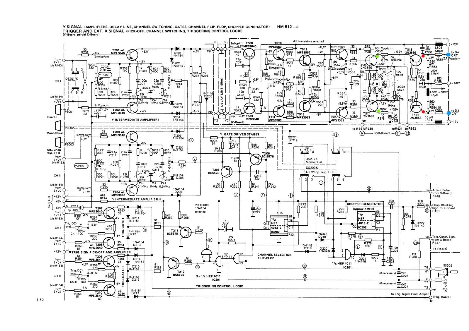
The blue dots are the connections to the Y plates of the CRT.
I shorted between the 2 red points, the trace jumped to the middle, as expected. Then I shorted between the 2 green points and the trace only dropped by 1 square, so does this mean the faulty transistors are T518 and T519?
If I measure the voltage at the collector of T519 it is 70V, not 42V as it should be. T518 measures 42V at the collector, so should I just change T519 or both?
Thanks again
Here is the schematic for the last stage of the Y amplifier:
The blue dots are the connections to the Y plates of the CRT.
I shorted between the 2 red points, the trace jumped to the middle, as expected. Then I shorted between the 2 green points and the trace only dropped by 1 square, so does this mean the faulty transistors are T518 and T519?
If I measure the voltage at the collector of T519 it is 70V, not 42V as it should be. T518 measures 42V at the collector, so should I just change T519 or both?
Thanks again
Hmmm... I'm not convinced without doing super accurate measurements.
The base is tied to the 12 volt rail (its a common base amplifier stage) with the signal applied to the emitter. Check those 51 ohm resistors and print are intact and that the base really is tied to the rail.
It might be worth measuring the voltage across the B-E junction but from what you say...
If you swap the transistors over the fault would change if it were faulty and the trace displace the other way.
Was just going to start to check base/emitter drops but noticed some faint smoke started coming from somewhere on the rear panel. The trace is now not filling the screen horizontally any more and if I turn the Y-Pos dials up and down, the trace shrinks slightly horizontally and starts to curve a little bit!
I may have to call it a day with this scope, it's been taking way more time than I have, so I may buy another scope. I can get an ex-demo Digimess 010 for £79 + vat. it's only 10MHz single channel, but pretty small and compact and will be ideal for what I want.
Oscilloscopes
Edit:
The trace is now a dot in the middle of the screen and when I use the Y-Pos knob the dot moves slowly to the right and then up a little and then back to the left!
Last edited:
- Status
- This old topic is closed. If you want to reopen this topic, contact a moderator using the "Report Post" button.
- Home
- Design & Build
- Equipment & Tools
- Help with a scope with a dodgy Y Pos