The box says that it is a Linkwitz-Riley 4th order ACOUSTIC DESIGN. 2-way.
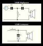
I don't see how it's 24db in the schematic. Looks like low pass is 12db and the high pass is 18db. Doesn't a 24db (I thought 4th order WAS 24 db) 4th order look similar to a doubled up 12db second order? Please help explain this for me, as I am clueless I am assuming that acoustical and electrical design are different??? Does it have more to do with Cap and coil values than layout?
I do have access to different order pictures, just didn't post. I just wanted to make sure there weren't other styles of 24 db 4th order xo's.
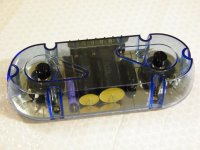
I do know that the potentiometer on tweeter is for attenuation. The woofer control seems to have a potentiometer that possibly makes minute adjustments in phase of woofer to compensate for timing issues brought upon by off axis and distant tweeter mounting? (On the schematic, the circle with P is the potentiometer). I forgot the symbol for pot when I did the schematic
I am trying to learn to make passive networks, so this is a good starting point to look at, and this unit was considered "higher end" or Sound Quality" production for car audio when it came out. I also have a Boston Rally crossover box, but it is more complicated and has quite a few resistors. I have no clue what is meant by "acoustical design" and how it makes a 12 or 18db crossover a 24. This is new to me.
I am going active crossover for part of my next home system, but will still use passive on some drivers. Hence my looking at this crossover design.
It does not say what crossover slope it is on the box, and I can't find any information online. I bought this when they closed out the line in 1998.
I am also looking for the T/S parameters of the Infinity Beta five (not X).
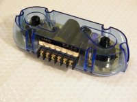
This unit also has what appears to by nice big capacitors of high quality for the tweeter, yet a little one for the woofer. Why? Would you not use a similar quality capacitor on the low pass, also? Just my thoughts. I know that the capacitor is smaller for the value, but it looks totally different as far as external build.
Thanks for you time. See attachments for reference, and my schematic. I was going to post this in the multi-way forum, but figured it would get move to the car audio forum.
Todd
1.5kHz crossover point
High pass:
c1 22.5uf
c2 14.8uf
L unknown
Low pass
c 42uf
L unknown
Pots say 2 ohm possibly?
I don't see how it's 24db in the schematic. Looks like low pass is 12db and the high pass is 18db. Doesn't a 24db (I thought 4th order WAS 24 db) 4th order look similar to a doubled up 12db second order? Please help explain this for me, as I am clueless
I am assuming that acoustical and electrical design are different??? Does it have more to do with Cap and coil values than layout?I do have access to different order pictures, just didn't post. I just wanted to make sure there weren't other styles of 24 db 4th order xo's.
I do know that the potentiometer on tweeter is for attenuation. The woofer control seems to have a potentiometer that possibly makes minute adjustments in phase of woofer to compensate for timing issues brought upon by off axis and distant tweeter mounting? (On the schematic, the circle with P is the potentiometer). I forgot the symbol for pot when I did the schematic
I am trying to learn to make passive networks, so this is a good starting point to look at, and this unit was considered "higher end" or Sound Quality" production for car audio when it came out.
I also have a Boston Rally crossover box, but it is more complicated and has quite a few resistors. I have no clue what is meant by "acoustical design" and how it makes a 12 or 18db crossover a 24. This is new to me.I am going active crossover for part of my next home system, but will still use passive on some drivers. Hence my looking at this crossover design.
It does not say what crossover slope it is on the box, and I can't find any information online. I bought this when they closed out the line in 1998.
I am also looking for the T/S parameters of the Infinity Beta five (not X).
This unit also has what appears to by nice big capacitors of high quality for the tweeter, yet a little one for the woofer. Why? Would you not use a similar quality capacitor on the low pass, also? Just my thoughts. I know that the capacitor is smaller for the value, but it looks totally different as far as external build.
Thanks for you time. See attachments for reference, and my schematic. I was going to post this in the multi-way forum, but figured it would get move to the car audio forum.
Todd
1.5kHz crossover point
High pass:
c1 22.5uf
c2 14.8uf
L unknown
Low pass
c 42uf
L unknown
Pots say 2 ohm possibly?
Attachments
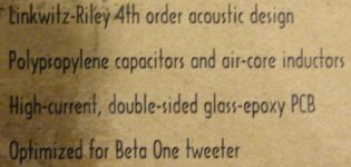
the 'acoustic design' is a hint. if I'm not mistaken, it means the crossover provides the 12db/oct and the woofer's natural HF rolloff is used as the other 12db/oct slope. when measured acoustically (a mic in front of the speaker) they add up, the resulting slope would be 24db/oct.
Hi, i'ts as djQuan says. The final acoustic response is what determinates the filter order.
This is a Morel mw144 driver suited with an electrical second order filter
that is one 0.5mH inductor and a 22uF cap. Between cap and ground there is a 2R2 resistor (solid line), and none (dotted line).
I suspect the second pot is to achieve something similar (to bend the LP curve as to follow an LR4 shape) Why they use a pot instead of a fixed R is beyond me..
Attachments
I see. It makes more sense now, thanks
This crossover was designed to be used with a specific tweeter, but not with one specific woofer. Maybe that is why it has the woofer control?
You had your choice of a 4 inch, 5.25 inch or 6.5 inch woofer.
I would suppose they would each respond differently to the crossover...
So, electrically, it is an 18db high pass and a 12db low pass.
How does a resister affect the circuit?
Thanks for all the info!
Todd
Aah!.. now it makes sense. The resistor mess with the filter QThis crossover was designed to be used with a specific tweeter, but not with one specific woofer. Maybe that is why it has the woofer control?
Different woofer, different way it reacts to this complex load, so, a sort of Q control.
But... tuning it by ear?
Cheers
J
- Status
- This old topic is closed. If you want to reopen this topic, contact a moderator using the "Report Post" button.