Long story short is i have the "power on , no protection" and if there is a way to confirm this diagnosis with a dmm and pc psu?
I bought a HD 8k back in '16 and it sat till my build was done. Got my truck back and it worked for a given total time of around 30 mins. As I was going through a smaller city I used my remote kill to cut the amp when I turned the amp back on and it sounded like one rca was unplugged. Cycling the amp later removed all sound from it. After sitting on it for a while the guy over at "Barevids" on YouTube made this video YouTube and after searching I found a board repair place close to me. I asked them if they could watch this video and follow his instructions for diagnosis, they said yes and according to them a what he says in the video is what has happened to mine. I found the type of zener diodes I need from a post here and I'm curious as to if there is a way for me to confirm this. Granted I only have access to a dmm and a pc psu, much application for all the board wizards out there.
I bought a HD 8k back in '16 and it sat till my build was done. Got my truck back and it worked for a given total time of around 30 mins. As I was going through a smaller city I used my remote kill to cut the amp when I turned the amp back on and it sounded like one rca was unplugged. Cycling the amp later removed all sound from it. After sitting on it for a while the guy over at "Barevids" on YouTube made this video YouTube and after searching I found a board repair place close to me. I asked them if they could watch this video and follow his instructions for diagnosis, they said yes and according to them a what he says in the video is what has happened to mine. I found the type of zener diodes I need from a post here and I'm curious as to if there is a way for me to confirm this. Granted I only have access to a dmm and a pc psu, much application for all the board wizards out there.
Assuming you know how to use a PC PSU to power the amplifier up then sure, you can run some checks with a DMM.
In the video he replaced an NPN transistor, a zenner diode, and two SMD capacitors. One of them being a small electrolytic cap.
To take voltage measurements, black probe goes on the ground power connector, I like to clamp mine to it so I have both hands free. Then I would take the red probe and probe that npn transistor to check the voltages. Pins 1 and 3 should have 15 volts, and pin 2 should have a slightly higher voltage. If the voltages look wrong then I would check the resistance to ground from pin 3. If the voltages look fine then I would move on to the pnp transistor and make the same voltage checks there. If anything looks abnormal in the voltages there then I would investigate that further. If everything checks out fine with voltages at both locations then you may be dealing with another issue entirely.
If you don’t know how to use a PC PSU to make a bench power supply to run the amp, then I would google how to do so. There are plenty of tutorials on how to accomplish this. Make sure you use at least a 10 to 15 amp automotive fuse in the B+ power wire between the amp and the power supply, and keep one hand in your pocket.
Hope this helps.
Hope this helps.
It definitely does and I appreciate it! Yes I do know how to use the psu, I'm competent with circuits in general. However I'm not when it comes to boards, logic etc. But is there any reason to worry about the gate resistors? I feel like I shouldn't long as I stay off that side of the board but that's an assumption.
I don’t see a need to pull the gate resistors. You can do all the checks and repairs necessary without even pulling the board from the case. If you did pull the board from the case there is the potential for the output mosfets to overheat because they are no longer clamped to the heatsink. So long as you’re not probing around the op amps and driver ICs there shouldn’t be any danger of shorting the output mosfets.
Last edited:
So long as you’re not probing around the op amps and driver ICs there shouldn’t be any danger of shorting the output mosfets.
Well as it stands now the amp appears to have a short between power and ground. I'm not sure if that is normal or not but when I attempt to power it up using a pc psu it trips. This is the first time I have tried powering it up since I took it out the truck. I'm hoping I'm doing something wrong but I've also got a suspicion that the place I took it to shorted something. Besides checking continuity between power and ground is there anythingelse I can do?
Do you read 0 ohms between the B+ and ground terminals?
Some PC power supplies go into protect due to the inrush current when powering large car amps.
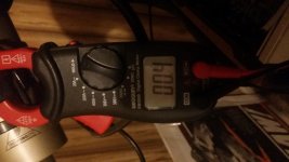
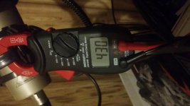
Well that didn't occur to me, it is an older psu (20 pin atx) and no it doesn't read 0. I apparently jumped to a conclusion. I'm assuming I'd need to use a resistor in line to prevent the in-rush. It probably doesn't help that I'm using a $15 meter from Walmart. But here are the results I got.
Attachments
. If everything checks out fine with voltages at both locations then you may be dealing with another issue entirely.
Well everything checked out but I did just notice this. Not sure on the value but I'm gonna guess there's supposed to be a resistor there. Since I've already got new zeners would it be advisable to go ahead and replace them or just leave it alone?
Attachments
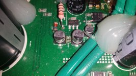
That missing component is a SMD capacitor. I’ll look when I get back to the shop to see if I have any information on what should be there.
As for the zenner diodes you bought to replace, did the ones that are already on the board check with the proper readings? With the DMM in diode check mode you should read somewhere close to 1/2 volt across it in one direct and open in the opposite direction. If it’s reading a short or really low then I’d say yes, replace them.
As for the zenner diodes you bought to replace, did the ones that are already on the board check with the proper readings? With the DMM in diode check mode you should read somewhere close to 1/2 volt across it in one direct and open in the opposite direction. If it’s reading a short or really low then I’d say yes, replace them.
That missing component is a SMD capacitor. I’ll look when I get back to the shop to see if I have any information on what should be there.
As for the zenner diodes you bought to replace, did the ones that are already on the board check with the proper readings? With the DMM in diode check mode you should read somewhere close to 1/2 volt across it in one direct and open in the opposite direction. If it’s reading a short or really low then I’d say yes, replace them.
Thanks, I've been told by another guy it's 100mf cap but idk. I'm also assuming the one on the opposite side should be the same correct? As for the diodes they read 750mv but I also think my meter is off bc it's an el cheapo from wally world I'll see if I can get my hands on a better one.
It should be identical to the one on the other side. If you get a better meter get one that can read capacitance. I looked through the schematics that I have and didn’t find one for that amp. I usually have several of these amps in the shop on any given month but no joy on that front. I did get a call today about a Taramps that is clipping and is supposed to be delivered tomorrow by it’s owner but I’m not sure what it’s gonna be.
750 mv is not a bad number. A little high if anything. Certainly not shorted so that’s good news. Your meter may be a little off but you’re in the ballpark.
Sorry about dropping this post abruptly but, I had a death in the family last week and I haven’t been in the shop much since then.
David
750 mv is not a bad number. A little high if anything. Certainly not shorted so that’s good news. Your meter may be a little off but you’re in the ballpark.
Sorry about dropping this post abruptly but, I had a death in the family last week and I haven’t been in the shop much since then.
David
Sorry about dropping this post abruptly but, I had a death in the family last week and I haven’t been in the shop much since then.
David
I'm sorry to hear that, my condolences to you and your family. No worries though take your time I'm in no rush at all.
I'm sure the shop local to me can measure that and get a matching one. I'm gonna assume it would be better to replace both so that they are from the same lot? Also with all this being said would you recommend following and replacing everything that was done in that YouTube video I posted earlier in the thread along with the cp27 cap and matching one on the other side. Since I've already bought the diodes and have no other use for them.
Based on what you’re telling me, the other components check out good. It seems like that one missing capacitor is keeping your amplifier from working. You can do what you want of course, but I personally don’t see a need to replace them. I’m not sure what equipment you have to remove and replace the other components, so I can’t say for sure if you might run the risk of creating more problems for yourself. To replace that one cap, you just need a decent soldering iron and a little bit of solder. To remove SMD components I usually use a hot air work station and then use a soldering iron and solder wick to clean the pads of old solder and then put on fresh solder and use a soldering iron to install the new components.
David
David
My plan was to get a electronic repair place local to me to do it all since they have the tools and whatnot. I've delt with them before and ate pretty knowledgeable so I guess I'm gonna get them to replace that cap and see what happens. Hopefully that is all that's what's wrong with it and it's not the diodes, pnp etc like in the video.
It is connected to the one on the right side of it.
Should I be checking anything related to this?
Also I went back and checked the npn and pnp trans and I'm not sure on the pin outs but on the trans that is on the same side as cp27. Pin 1 (going from left to right) I have 15v, pin 2 22v, pin 3 15v. The opposing trans has equal and opposite voltages.
Another note I checked the zeners again and before I did I tried to adjust my dmm to match what the meter on the amp says (11.5v) since it doesn't have any range on the DC or AC I got it close as I could. Needless to say the diodes on the amp are reading 640mv across them however the ones I bought are reading closer to 820mv. I'm more inclined to believe the new ones are reading correctly or at least closer due to the meter I'm wondering if that has anything to do with it as well.
It’s possible that something in the circuit that the diodes are connected to are loading them down a little bit when you are reading them with your meter. You do get a true reading when they are not mounted in the circuit. It doesn’t sound like you are having an issue generating your +\- 15 volts. I’m inclined to believe you have a different issue going on with the amp than what you originally thought.
Have you tried playing some music through it with it connected to a speaker to see if it is working? Sometimes the RCA jack can get damaged. One of the three legs of the RCA jacks that connect it to the board could have broken and cause the amp to play sometimes and sometimes not. So check the RCAs as well.
Have you tried playing some music through it with it connected to a speaker to see if it is working? Sometimes the RCA jack can get damaged. One of the three legs of the RCA jacks that connect it to the board could have broken and cause the amp to play sometimes and sometimes not. So check the RCAs as well.
- Status
- This old topic is closed. If you want to reopen this topic, contact a moderator using the "Report Post" button.
- Home
- General Interest
- Car Audio
- Help confirming a diagnosis