I'm finally taking the plunge and building an RIAA preamp from schematics, and after some research I've arrived at Jim Hagerman's octal version of his Cornet. While I have a few years of experience fixing tube gear and building packaged kits, I've never undertaken a project starting with just schematics and a parts bill, so this should be a fun challenge.
Because the PCB is no longer available, this build will be constructed point to point (not turret board). I'm currently working on ordering parts and have a few questions...I'm hoping some of you that have experience building it can chime in:
1. Other than the CCS on the output, are there any changes/improvements made in the Cornet ver. 2 that I should implement in this design? Can I use the same component values for the CCS circuit on the 6SN7?
2. What coupling capacitors would work well for this preamp that don't break the bank?
3. Do you have any tips for proper grounding and silent operation, or do you know some resources I should look at before I start?
4. Anything else I should know?
Thanks in advance for the help.
Schemos:
Cornet octal
Cornet 2
Last edited:


You really bring a unique aesthetic touch to your projects. I like it! What are those film caps? They look budget-friendly.
Also can someone point me to some chassis that have a square hole pre-cut for power entry? I don't have an easy way to cut it out myself.
Like this:
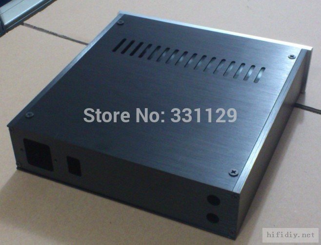
Also can someone point me to some chassis that have a square hole pre-cut for power entry? I don't have an easy way to cut it out myself.
Like this:
Attachments

Dubwoofer,
It is simple and cost effective to buy a square hand file made for metal, drill some holes near the corners of your rectangular cutout (inside the layout marks), and just file away. Any non-perfect edges will probably be hidden away under the lip of your IEC socket. I've used this method tens of times and it never takes more than 10 or 15 minutes of good honest work for aluminium chassis, a bit more for steel.
It is simple and cost effective to buy a square hand file made for metal, drill some holes near the corners of your rectangular cutout (inside the layout marks), and just file away. Any non-perfect edges will probably be hidden away under the lip of your IEC socket. I've used this method tens of times and it never takes more than 10 or 15 minutes of good honest work for aluminium chassis, a bit more for steel.
I've used that method a few times in the past to install rocker switches and I'll resort to it if I need to, but it's worth it to me to put out a small premium and have an enclosure with clean cutouts ready to go.
Can I use an aluminum chassis for the build, or is steel a better choice?
Can I use an aluminum chassis for the build, or is steel a better choice?
I did some research on the subject... The consensus seems to be, aluminum is easier to work with but steel is stronger and has better shielding. Since my metalworking tools are severely limited, aluminum is probably the way to go.
Does anyone here have experience with HIFI 2000 enclosures? I just discovered them and they look excellent...Right now the Slimline 1U is probably my top contender for a chassis, and the store will CNC holes-at a price
Slimline 1U – diyAudio Store (BETA)
My only concern with that one is, will the top cover support the weight of the transformer and not flex when inserting/removing tubes?
My only concern with that one is, will the top cover support the weight of the transformer and not flex when inserting/removing tubes?
No way. Top cover is 1mm steel.
I used some (not so large) chinese boxes with 3mm aluminium top cover for my preamp.
items in store on eBay!
I can't find anywhere on the site that specifies the thickness of the aluminum covers.
See the original manufacturer's website:
Frontale 10mm coperchi in alluminio 3mm
3mm.
But 450mm width is too large.
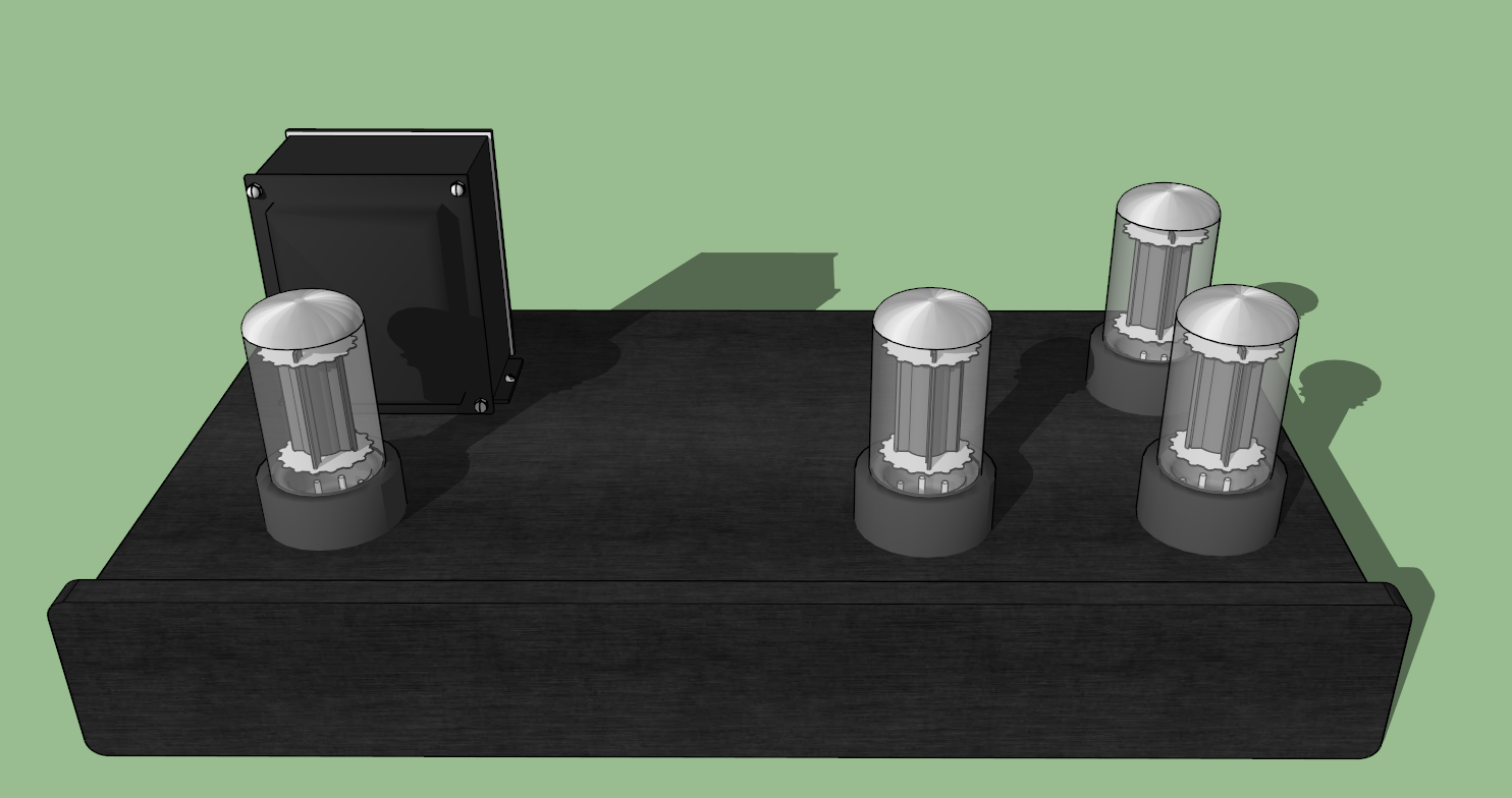
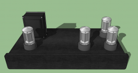
Just for kicks I modeled the preamp in sketchup with the Galaxy enclosure and worked on a layout. Here's what I arrived at:
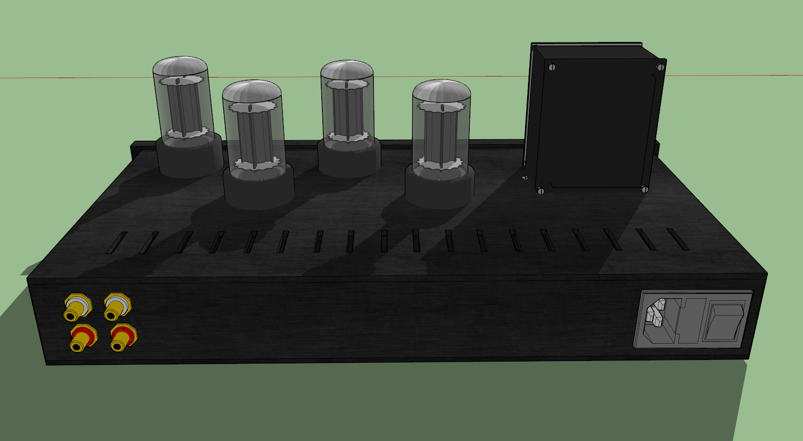
I really like the size and it's aesthetically pleasing...If the top cover is rigid enough I think I'll go this route.
I really like the size and it's aesthetically pleasing...If the top cover is rigid enough I think I'll go this route.
Attachments

Last edited:
I think the power transformer is far too close. It should be placed as far away from the tubes and audio circuitry as possible. The tubes in the first stage of the pre-amp should be located within a couple of inches of the input RCA jacks, or you may need to use coaxial cable to the grids, and it might be better to place the output RCAs well away from the inputs.
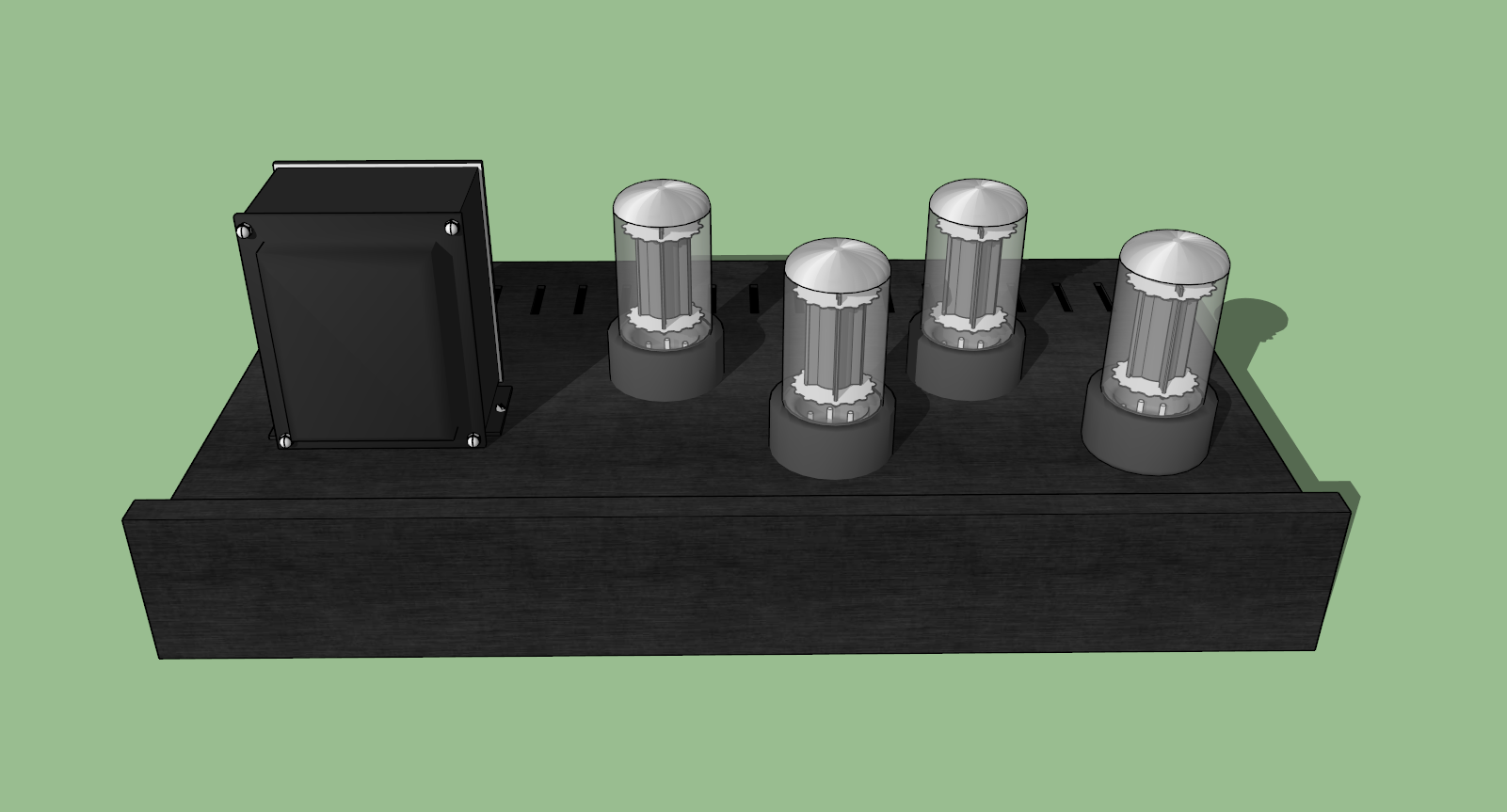
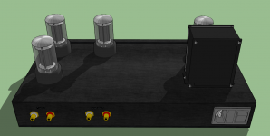
Thanks for the advice. How far, realistically speaking, should the transformer be from the audio section? If I substitute the vented cover for a blank one and move things around a bit I come up with the following:
Also, am I correct in thinking that the transformer should be rotated 90* from how it's shown?

Also, am I correct in thinking that the transformer should be rotated 90* from how it's shown?
Attachments
Last edited:
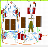
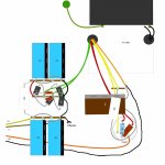
Here's my proposed layout for the audio section created in DIYLC. Please forgive the newb question, but how should I ground everything together? The ground symbols were just for my reference and don't delineate chassis connection. Are there any problems that stand out?

Attachments
Last edited:
Is my grounding correct?
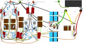
I worked out the full layout and added in the recommended CCS. Does the grounding look right? Is it OK to use pin 1 on the 5Y3 to solder R20 and C9 to?
All parts have now been ordered...I decided to go with the basic red PP coupling caps from AES for now just to get everything working and upgrade later on.
Attachments

Thanks for the advice. How far, realistically speaking, should the transformer be from the audio section? If I substitute the vented cover for a blank one and move things around a bit I come up with the following:
Also, am I correct in thinking that the transformer should be rotated 90* from how it's shown?
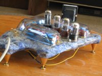
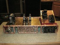
That looks much better. Here is a pic of my Low-Mu preamp. I kept the power and signal paths as far away from each other as possible.
Attachments
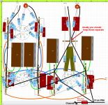
No. Too many chassis connections. Never EVER connect your reservoir cap to chassis!Does the grounding look right?
Attachments
Last edited:
Thanks for marking it up with your notes. Hopefully this one is more correct (also fixed L ch R9 so it goes to the plate instead of the cathode). I couldn't find much info about hum blocking networks in line with the ground. Is there a specific circuit you would use?
Will the long-leaded components from the output cathodes to the jacks be a problem? I'm wondering if I should make them shorter and use shielded wire for the final stretch.
Will the long-leaded components from the output cathodes to the jacks be a problem? I'm wondering if I should make them shorter and use shielded wire for the final stretch.
Attachments
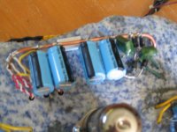
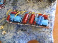
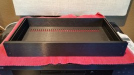
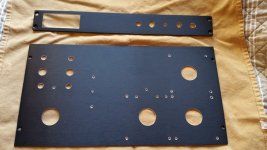
Most of the parts arrived this week  . To my amazement the chassis only took two days to get here from Italy.
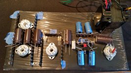
I layed out some of the major components on the top panel to help me finalize where I want to make the holes. It's going to be a tight fit with those plate supply 'lytics but I think it's doable.
Pardon the phone camera pics
. To my amazement the chassis only took two days to get here from Italy.I layed out some of the major components on the top panel to help me finalize where I want to make the holes. It's going to be a tight fit with those plate supply 'lytics but I think it's doable.
Pardon the phone camera pics
Attachments
Last edited:
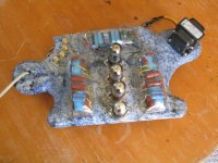
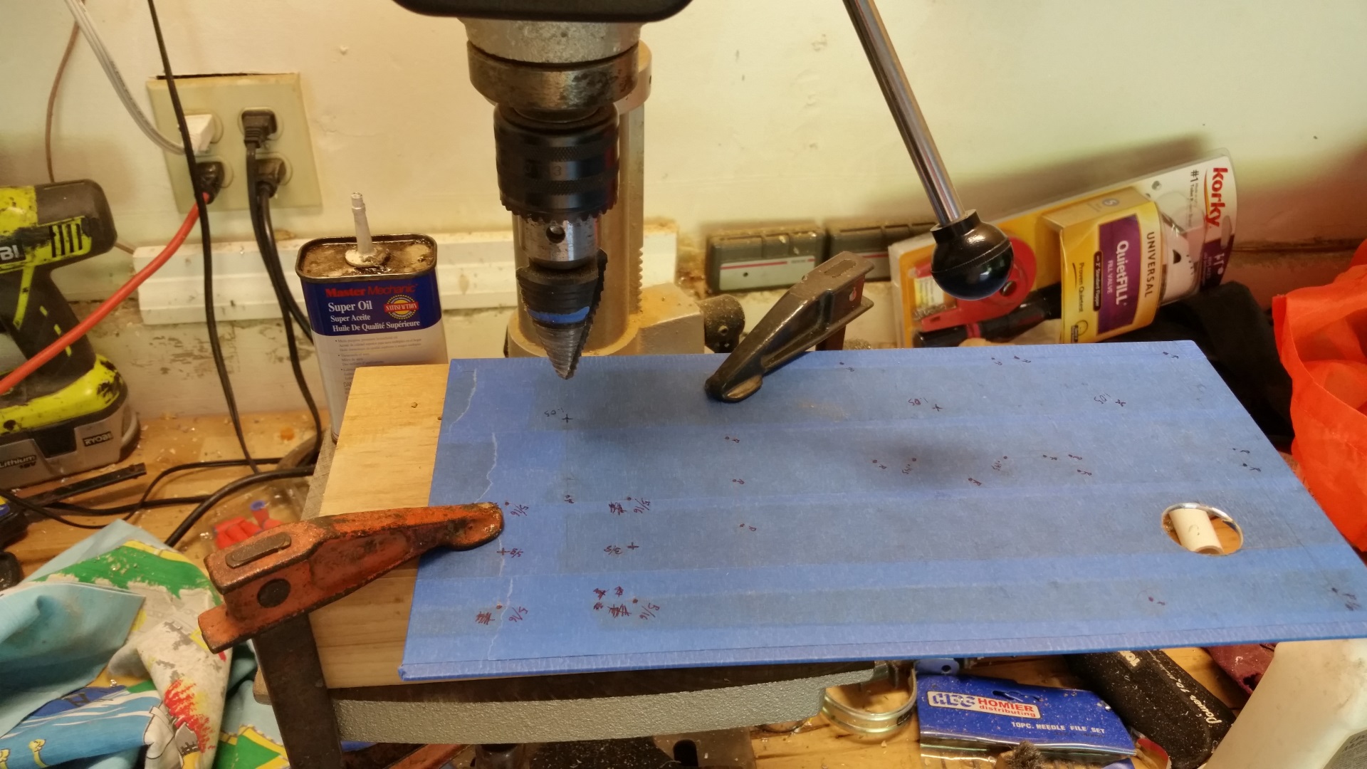
A productive weekend I had. I wrapped the panels in painters tape and marked them up with the hole layout.
Drill, baby, drill!
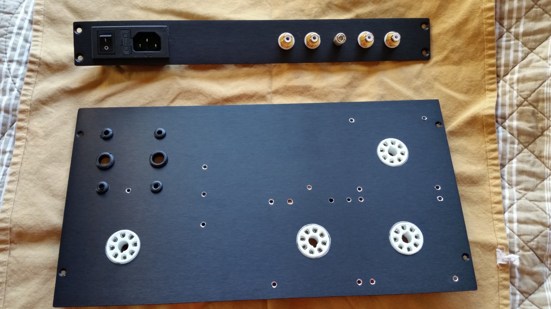
It's beginning to take form... Test fit with some parts... By mistake I ordered a power inlet that has the switch in the wrong orientation. Fortunately there's a model variant where it's flipped.
Drill, baby, drill!
It's beginning to take form... Test fit with some parts... By mistake I ordered a power inlet that has the switch in the wrong orientation. Fortunately there's a model variant where it's flipped.
Attachments


Last edited:
- Status
- This old topic is closed. If you want to reopen this topic, contact a moderator using the "Report Post" button.
- Home
- Amplifiers
- Tubes / Valves
- Hagerman Cornet Octal planning help and build