New member here - recently got my grubby paws on what appears to be a well cared-for / clean 1st-gen FET-9 from the original owner.
I HAVE searched for related posts, but most of them are several years old.
My thoughts / questions:
Given its almost 30 year age - I plan to preemptively replace only those components that are prone to leakage / degradation, which points to the Electrolytic Caps. I have also read that the selectors and Pots are of a SEALED type - so NO spray-cleaner on those.
I’m also a big believer in the “if it ain’t broke - don’t fix it” theory, so I want to address potential problems, but with a MINIMAL approach.
Q1. I’m thinking Panasonic for the Power Supply Section and Silmic II’s for those associated with the Signal Path Biasing. Is that still recommended?
Q2. Are there any other items worth attention on the initial go-Round?
Looking at the External Power Supply - my impression (no insult to the original designer intended) is that it seems pretty “wimpy” for something used to power a high-end unit. I know that this IS a pre-Amp, and it has a relatively low current draw, and that the “fancy-pants” regulation takes place on the main unit Motherboard. However- My Product Research on the FET-9 & 10 family has shown the substantially upgraded units that were provided later.
Initially, I plan to just update the filter caps and try it. -BUT-
Q3. For those of you who have Upgraded or Replaced the Power Supply:
3A. Was it worth the effort and cost?
3B. What did you actually do?
Nelson Pass replied to a post from someone regarding capacitors to replace on a FET 10 HL, if you search for FET 10 you may find it. It was within the last year, just don't remember when, however, I would follow what Nelson has to say about capacitors.
I bought a FET 9 in 1985 along with an S300 amp, big mistake selling those. My FET 10Pe is still my favorite audio component.
I bought a FET 9 in 1985 along with an S300 amp, big mistake selling those. My FET 10Pe is still my favorite audio component.
Also, does anyone have or know where to find labeled PCBA drawings or photos for the Boards within the “plain Jane” version of the FET-9?
I found a copy of the Service Manual that has Schematics, but it’s hard to tell which component is which and the boards are not labeled/marked. I’ve found stuff for various versions of the 10, but NOT for the basic-9.
I found a copy of the Service Manual that has Schematics, but it’s hard to tell which component is which and the boards are not labeled/marked. I’ve found stuff for various versions of the 10, but NOT for the basic-9.
I changed the original (Mallory) caps in the power-supply for my FET10.
I honestly wasn't able to hear any difference at all.
Next I had Teddy Pardo build a replacement-supply. (Yes, I was lazy)
This made a huuuuge difference!
It clearly helps the amp reveal just how epic it really is!
I haven't made any changes to the amp itself.
I honestly wasn't able to hear any difference at all.
Next I had Teddy Pardo build a replacement-supply. (Yes, I was lazy)
This made a huuuuge difference!
It clearly helps the amp reveal just how epic it really is!
I haven't made any changes to the amp itself.
INITIALLY - I'm planning to replace just the Electrolytics, including those within the External Power Supply (My 1st-gen FET-9 does not appear to have any potentially troublesome Tantalums in it.)
That will let me play with my new toy (Hopefully, REALLY bring-out what my AR TT / Shure V15-Vmr can do - I'm sure that the Phono Stage should blow-away the one in my NAD Receiver that is presently serving Pre-Amp duty.)
THEN (Later) - I plan to build one of the Upgraded Power Supplies that others have made for the FET-10 Series. A project like that should be relatively simple and is well within my means and abilities. [I figure that a little Judicious "overkill" can't hurt - so long as it's done right and relatively inexpensive to do so.]
Put Power Supply on Voltmeter and Oscilloscope, to attempt to get a fairly accurate evaluation of the condition of this "oldie but goodie":
V+ = seems OK, nearly flat output at about 29.8 VDC
V- = seems OK-ish, about 31.8 VDC with around 40 mV of ripple on it (iffy cap?)
I assume that the secondary regulation should handle any difference, but before attempting that, I'm going to replace the Power Supply Caps (they're arriving 2-day!)
Does anybody have pics / layout drawings of the FET-9 "Plain Jane" version that show component names/numbers and what Voltages / Signals the various standoffs carry?
(MY version does not have the 20-pin connectors between the Mobo and the Phono / Line-Stage Board. Gold-Plated stand-offs, washers, and Allen-Key screws are used to carry Voltage and Signal between the boards.)
Zen Mod's linked page shows the "/e" Version, which is different from mine. Tried E-mailing the "current" Threshold, but wonder if there is anybody there NEmore...
Replaced caps in separate Power Supply and Output Voltages remained about the same.
How concerned should I be about the difference between V+ & V-?
(Do they “Even-Out” under load? Or, Does the Secondary Regulation on the Main Unit Motherboard take care of this?)
I KNOW that there are Trimpots for fine-tuning the Regulated V+ & V-. The Service Manual specs what to set these at, but my copy does not show WHERE the Test Points are for this measurement. A semi-educated guess would dictate seeking and checking 3 of the Gold-Plated screws / stand-offs that are used to carry Power & Signal between the Phono/Line-Stage Board and the Motherboard, (logically, 3 of them on the end nearest to the Power Regulation Section) but it would be nice to know for certain which are which.
(There are about 16 such cross-connects and I can make some logical assumptions about what such connections SHOULD be “present”). I believe that I have schematics for the FET-9e, which uses about 6 separate modules for Regulated Power, Line, & Phono in L & R pairs for each, and uses 20-Pin connectors in place of the plated standoffs & screws that are used on mine, but I am certain that the circuits are still VERY similar and I CAN draw some logical parallels between that one and mine. (Mine pre-dates the Op-Amp-Based Servo Control biasing circuitry shown on the more modern “e” model.)
The way I guesstimate it, there SHOULD be:
-Raw Phono IN L/R = 3 or 4 points [trace to Jacks separate rate or combined Signal Ground?]
-Amplified Phono OUT = another 3 or 4 points [to Mobo for Source Selector Switches]
-Raw Line IN = [from Source Selectors] 3 or 4 points
-Line OUT = [To Volume Controls / Tape Source Selectors] 3 or 4 points
-Regulated Power IN [maybe multiple sets] = but at least 3 or 4 points
[I can find / identify these by fishing-Around with my Voltmeter and checking continuity]
Zen-Mod, can you PLEASE double-Check your archive of Literature, and see if you have a copy of the 1st-Gen Service Manual and / or the Circuit Board layout / labeling drawing or pics and maybe the schematic for this particular model?
One last item about the Electrolytic Caps for this unit:
-I know that Nelson Pass has recommended ELNA Silmics (Silmic II)
-However, it seems to be difficult to find these in the proper PHYSICAL size and Voltage for my unit
(Checked both Mouser & Digi-Key, and Newark)
-The 4 470uf Caps on the Mobo are hard to find in the shorter 35V version
(There may be room to “lay-over” some slightly larger 50V ones on their side that I got before realizing that they are too tall by about 7mm)
-The 2 “shorties” 470 if in shorter still 25V version
I want the replacements to be DURABLE, so I want sufficient Voltage Margin (rating vs applied) plus best Service Life available. What are thoughts on Nichicon KA series, which appear to be relatively new, and have higher temperature and service life ratings, while also being intended for Audio applications? I know that Nichicon has a good reputation for quality and this series seems to be more readily available in the sizes that I need.
Last edited:
Mine appears to be essentially the same as the one that renehc posted
See previous thread “Threshold FET Repair Story”
(Same orange Mallory caps in Power Section and blue shorties at Phono end of upper PCBA = the end with the DIP switches for Cartridge Loading...)
Mine has S/N 220, so I would guess pretty early production
See previous thread “Threshold FET Repair Story”
(Same orange Mallory caps in Power Section and blue shorties at Phono end of upper PCBA = the end with the DIP switches for Cartridge Loading...)
Mine has S/N 220, so I would guess pretty early production
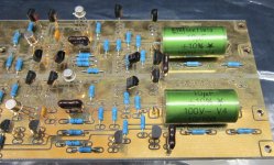
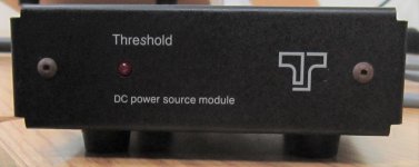
PICS FET-9 1st-Gen (Non-"/e")
OK - I shot a bunch of pics in an attempt to capture both the whole thing and the major parts.
This one has the original "extra-wimpy" Power Supply (Already re-capped)
As you'll see in the pics - this version does not have separate daughter cards for power, line stage, and phono.
-Secondary Power Regulation is on the end of the Mobo opposite from Phono
-Phono and Line-Stage are combined into a SINGLE Circuit Board Assembly
-Connections between the two Circuit Boards are via (16) gold-plated stand-offs
I Have not replaced the Electrolytics on either of the main unit boards yet.
How concerned should I be about attempting to "Match" Capacitors in equivalent positions for L&R and +V&-V? (I figure that in the least, it cannot hurt to try - but all that I have for measuring the caps is a Fluke 115)
(Gotta' shrink the photos - Be right back...)
Last edited:
PICS FET-9 1st-Gen (Non-"/e") Part II
Here are the pics:
Here are the pics:
Attachments
-
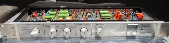 FET-9_Front-View.jpg854.6 KB · Views: 99
 -
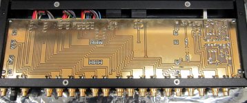 FET-9_Mobo-Bot.jpg435.8 KB · Views: 97
 -
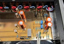 FET-9_Mobo-Pwr.jpg420.2 KB · Views: 96
 -
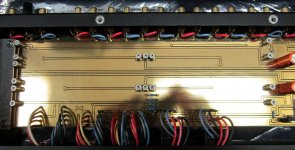 FET-9_Mobo-Stand-Offs.jpg389 KB · Views: 90
 -
 FET-9_PL-Line-End.jpg369.6 KB · Views: 97
 -
 FET-9_PL-Phono-End.jpg379.7 KB · Views: 77
 -
 FET-9_PL-Phono-Line-PCBA.jpg466.2 KB · Views: 68
 -
 FET-9_Top-View.jpg329.6 KB · Views: 68
 -
 FET-9_XPwrsuply-F.jpg365.3 KB · Views: 63
 -
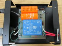 FET-9_XPwrsuply-Top.jpg468.6 KB · Views: 66
It’s ALIVE!
Fired her up for the first time yesterday.
(Have not tried the Phono circuits yet - maybe tomorrow.)
My ELAC Uni-Fi speakers suddenly seem to have more low-end “grunt”
Cleaner punch/ attack.
(But then again, I’m comparing a $350ish “bang-for-the-buck” NAD with a $2K-ish separate from about the same era.)
Initially seemed to have a little intermittent hiss on voices with sibilants and stuff like brushed cymbals- but that seems gone today (is this something that happens with New Electrolytic Caps that may have been sitting around for a while?)
Should probably re-cap & clean pots on that old NAD and give to nephew or sell for Speaker Upgrade fund...
- Status
- This old topic is closed. If you want to reopen this topic, contact a moderator using the "Report Post" button.
- Home
- Amplifiers
- Pass Labs
- FET-9 Restoration / Update