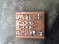
Is the pcb for the 150 w amp suitable for esp P3 amp??? Ill be cutting the collector tracks and will put 220 ohm resistors in series with the collectors of Q1 and Q2 and bypass D1 R10 and R12. I have attached the P3 diagram and the 15o w amp pcbs and ckt diagram .
Attachments
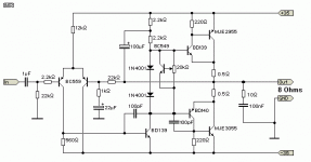
You don't need to cut the collector tracks.
Bend the transistor collector lead up through 180degrees. Solder on a collector resistor pointing down. The new three legged device will fit the old pad arrangement.
Add pads for base stoppers on all your driver and output devices. Again a bent base lead with added resistor allows for no PCB modification.
Add a resistor to convert the input C (change the C from 100pF to somewhere from 330pF to 1nF) to an RF R+C filter.
Add HF decoupling to the collector leads of the output devices.
Add MF decoupling to the supply rails near the output devices.
Add MF decoupling near the input stage supplies.
Last edited:
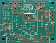
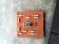
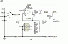
Thanks a lot. Here are the pics of my P88 preamp im goin to use with the amp. Im using the version ROd used for his Gainclone amp project. i hav not yet mounted the output caps. i was wondering whether i should use input caps to protect my source incase the opamp fails.
Attachments


- Status
- This old topic is closed. If you want to reopen this topic, contact a moderator using the "Report Post" button.
- Home
- Amplifiers
- Solid State
- ESp P3 amp on Cheap 150w amp board