I'm about to start building a single ended amp on a 12x8x3 aluminum enclosure. (I need the space for a beginner) it's going to be point to point and I'd like to learn how to use turret boards for the capacitor bank
I want to do it long ways (inline)with the transformers in the back then the output stage and finally the 12ax7 input at the front.
My questions are..
-What size screws are best?
-Is it ok to mount phenolic terminal strips before each tube and make the connections there before jumping to the tube pins?
-i want to do buss type grounding scheme,but I'm unsure of how to route it with the speaker terminals in the back. Shouldn't it start at the first filter capacitors -output tubes-speakers-then connected to chassis at only the input stage?
-what is used to suspend and isolate the 12-14 gauge bus bar in the air is it goes from stage to stage
-do you clock the tube sockets so that certain pins face each other for short wire lengths?
-can the feedback, zobel circuit and speaker +&- land on a terminal strip. Then from there take 2 wires to the speaker terminals.
-should the feedback wire be a shielded design and what type.
-is it ok to use solid core wire to make neat bends (is pre tinned stranded even better for this?)
-undecided on weither to mount the choke and output transformers on the underside of the chassis.
I know it's a lot of questions and I appreciate any help I can get. I'm right in the middle of ordering supplies and I'm stuck on a few things.
My 2 cents are>
Seems you are on the right way, according Morgan Jones author/Valve amplifiers, alu is the best metal to amp chassis, said it I could add if your amp dont generate alot of heat, what seems the case, you could try an 8mm transparent acrylic chassis or table only with sides in real wood, to get better safety on HV isolation and good looking in the night, no need painting too.
Seems you are on the right way, according Morgan Jones author/Valve amplifiers, alu is the best metal to amp chassis, said it I could add if your amp dont generate alot of heat, what seems the case, you could try an 8mm transparent acrylic chassis or table only with sides in real wood, to get better safety on HV isolation and good looking in the night, no need painting too.

Considerations:
1) Heater wiring. That can dictate the orientation of the tubes so that it is located in an optimal way around the edege of the chassis, away from small signal wiring.
2) You are going to have to get to tube pins for measurements, so tag boards can help unclutter the layout.
3) If possible keep the values written on the components visible - it helps later.
4) I use DIYLC to mock up the layout with real sizes for the components, and refine the layout as much as possible.
Your enclosure would seem to be quite small bearing in mind there will be 4 transformers.
Your chassis is only 3" deep, so all the iron will have to go on top, except the choke.-undecided on whether to mount the choke and output transformers on the underside of the chassis.
jeff
Last edited:
A few answers:
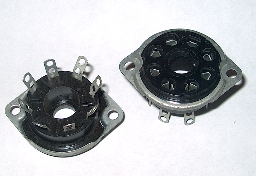
You'll need #2 machine screws to bolt the sockets to the chassis, get some toothed washers or kep nuts to make them secure. #4 or #6 will be needed for the terminal strips, and probably something bigger for the transformers. I get these online in bulk for a good price (and these are typically sizes I can't find in a store, especially in shorter lengths.)
I usually arrange the sockets based on where I want to put the heater wiring, but other considerations might come in to play.
You can suspend a bus bar on regular terminal strips, or individual terminal posts.
Solid core is fine, and easier to keep the ends neat.
I like to use twisted pair or shielded for the feedback path, and ground the output transformer to that part of the circuit.
A compromise on wiring sockets/terminal strips is to mount all the parts on terminal strips/terminal boards except for grid or screen stoppers mounted between a terminal strip and a socket pin, to keep the lead short, which is ideal for that usage.
Laying all your components out on a table or bench and doing a few sketches on scrap paper helps. There's a few general rules with layout, power supply as far away as poss from the input end, all wires, links etc as short as possible, heater wiring tucked into the chassis corners, if any other wiring crosses AC heater wiring it should do so at 90 degrees.
For mounting stuff I use standoffs both nylon and metal types and I use old ceramic standoffs which are great for ground buses. Caps can be secured with purpose made cap clips or I've used 13mm ( half inch) copper pipe, cut and bent. I use a few bolt/screw/nuts sizes - M2.5, 3mm, 4mm & 5mm for big stuff like mounting tfmr's. I also have jars full of washers, screws and other bits pulled off old TV's etc.
For chassis I used baking trays in my last amp build, these are the trays used in school kitchens etc, they're thick ali and look good when painted. Here's my channel on youtube - https://www.youtube.com/channel/UCtWTo2BUtf5jk16GkCVl4fA you might find a few tips and tricks on there though I'm not the best video blogger. Lastly check out The Valve Wizard site, it has loads of tips as regards heater wiring etc.
Andy.
Considerations:
1) Heater wiring. That can dictate the orientation of the tubes so that it is located in an optimal way around the edege of the chassis, away from small signal wiring.
2) You are going to have to get to tube pins for measurements, so tag boards can help unclutter the layout.
3) If possible keep the values written on the components visible - it helps later.
4) I use DIYLC to mock up the layout with real sizes for the components, and refine the layout as much as possible.
Your enclosure would seem to be quite small bearing in mind there will be 4 transformers.
What are tube pins?

You'll say that until you've done the wiring and it's been not enough space anyway, that's how it is whenever I build anything at least 😂I vastly over estimated my enclosure needs....lol View attachment 1129516 View attachment 1129516
I vastly over estimated my enclosure needs....lol View attachment 1129516 View attachment 1129516
Honestly it's way easier to develop good habits by starting in a big enclosure, the margins for a quiet layout are greatly increased. Is that one of the Bud industries boxes or Hammond? My most used size is the 10x8x2.5" Bud industries AC-1418.
12x8x3 I got it off Amazon for a nice discount. I went with the 3 inch because I have a iec plug for the side with built in fuse and switch. It's kinda tall and it allowed me to keep my primary wires to one side of the enclosure.Honestly it's way easier to develop good habits by starting in a big enclosure, the margins for a quiet layout are greatly increased. Is that one of the Bud industries boxes or Hammond? My most used size is the 10x8x2.5" Bud industries AC-1418.

I'm all for big chassis - mine are 2U size, so 420mm wide and 300mm deep. I also frequently use two chassis with the half width 2U face plates which are either 9.5" or 10.5". Better if the transformers and chokes are large and heavy. Space gets used up fast, considering that big capacitors mostly sound better for a start.
The transformers are what's called for in the thread over at audiokarma. They are tiny, but I don't have the budget for larger.Buy bigger output transformers or use that enclosure as a bath : ) They do look a bit lonely up that end, space em out a bit perhaps?
Andy.
At least I have the space for later.
 https://audiokarma.org/forums/index...ore-out-of-the-8600-series-a-lot-more.665735/
Any good threads discussing what type of motor run capacitors to use?You will have 5 tubes and 4 transformers from the schematic, and many here like to fit a motor run capacitor to augment the power supply, so I think it will still be tighter than you think.


Motor run caps they are usually film and low ESR, and add a bit of umph to the PSU.Any good threads discussing what type of motor run capacitors to use?
- Home
- Amplifiers
- Tubes / Valves
- Enclosure building