So,where to begin.My good freind have at home a long time some Grundig NF-1 amplifier with ecc83 and ell80 tube pro chanel.He now have buy some used hammond transformer with 10Kohm primar and 0-4-8 ohm sekundar windings.And this transformer hase the UL taps to.So the question is,is it posibile to run the ell80 tube in this NF-1 design in UL mode,so the screens will be conected to the UL taps(40%) or no???Can he try this just to see if he will like the sound of ultralinear or is pentode bether for him??Plese for help guys.
Hi Esteban,
...thanks for the answer.So is no problem at all,and he must not insert or use some other parts for this UL option.He just must cut the traces to grid conections and conect each grid with hammond UL taps.Will he need some screen grid stopper in this case or no??I have see,some design have some screen grid stopper on power tubes in UL mode.
...thanks for the answer.So is no problem at all,and he must not insert or use some other parts for this UL option.He just must cut the traces to grid conections and conect each grid with hammond UL taps.Will he need some screen grid stopper in this case or no??I have see,some design have some screen grid stopper on power tubes in UL mode.
You going to find five taps, they are: Plate one, G2 one, center, G2 two and Plate two.
You have a pinout of the transformer ? If not: Take an Ohmeter, Try to measure in the lowest range, the resistance of they. The major is between the plates, equidistant with the centre. Then in a little difference you can identify the UL tabs.
You have a pinout of the transformer ? If not: Take an Ohmeter, Try to measure in the lowest range, the resistance of they. The major is between the plates, equidistant with the centre. Then in a little difference you can identify the UL tabs.
The NFB is the same, take care of the phase, first of all, tray without NFB and then, tray to connect to the output of the major winding of the secondary, when you connect it in the right position you will note the amplitude of the sound going down, and the sound became more deep or dark. But less speed at all.
You can change the resistance in series with the NFB in this case are the 2k7 one from the cathode of the first ECC83
You can change the resistance in series with the NFB in this case are the 2k7 one from the cathode of the first ECC83
Hi Esteban,
....thanks verry much for your answers and help.Like you see my knowledge about tube amps is limited.I have put together some transistor amps,but tube amps are totaly another league.I will go to my friend tomorow and try out your recommendations,than we will see what is the diference in sound")
....thanks verry much for your answers and help.Like you see my knowledge about tube amps is limited.I have put together some transistor amps,but tube amps are totaly another league.I will go to my friend tomorow and try out your recommendations,than we will see what is the diference in sound
I Had the same amplifier, in Argentina, long time ago, and treasures of this, are the transformers. The other choice is connecting in triode mode, the only problem is the output impedance that going down but you can manage it connecting a four ohms speaker in the eight tap one and the charge going to halve. 5000 ohms. The sound of this amplifier is sweet. If you not can find ELL80 you can putt two EL95 or there are other twin tetrodes with a common cathode used in RF. The vintage valve is place where they discuss about weird valves for use in Audio. 6360 or QQE03-12
Last edited:
Hi Esteban,
.....hm verry interesting option to drive the tube in triode mode.But the power will be maybe to low in this case.But I could try this out.Plese tell me if the speakers are 8 ohm impedance,how than to become 5000 ohm primary on the transformer??Becouse you sayed to conect 4 ohm speakers on 8 ohm tap.
.....hm verry interesting option to drive the tube in triode mode.But the power will be maybe to low in this case.But I could try this out.Plese tell me if the speakers are 8 ohm impedance,how than to become 5000 ohm primary on the transformer??Becouse you sayed to conect 4 ohm speakers on 8 ohm tap.
Because the transformer in true is an impedance adaptor, the relation ship between the primary and the secondary lets to adapt the 8 ohms to the 10000 ohms of the load.
If you connect the 8 ohms loudspeaker to the 4 ohms tap, the valve going to see 20000ohms in front.
In the opposite way if you connect one 4 ohms to the 8 ohms tap the valve going to see a load of 5000 ohms.
I counsel to you that get a book that is easy to understand and cheap, the name is Valve Amplifiers, Morgan Jones 4th edition.
Best regards
Hi Alexander,
thanks for your reply and schematic.Yes thats the way I will try out on this grundig NF-1 amplifier.Plese tell me if Im right,so the 2,7Kohm resistor with the litle choke in series is the NFB for this amp and is conected with speaker output.So can I conect this with the new transformer 8 ohm output also or is this not needed???
thanks for your reply and schematic.Yes thats the way I will try out on this grundig NF-1 amplifier.Plese tell me if Im right,so the 2,7Kohm resistor with the litle choke in series is the NFB for this amp and is conected with speaker output.So can I conect this with the new transformer 8 ohm output also or is this not needed???
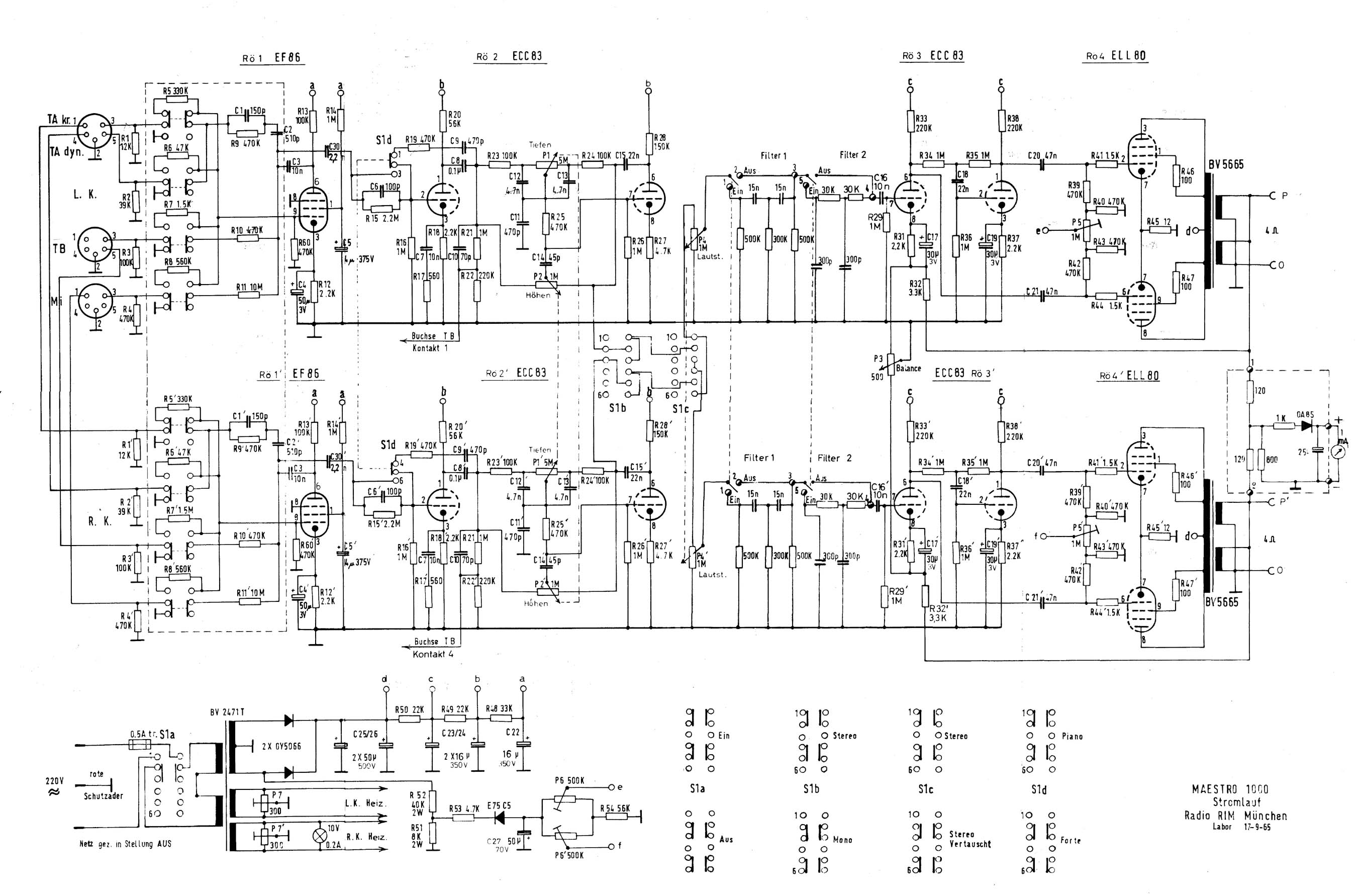
Hello ,
here is the complete description , but only in german language , sorry .
The feedback loop here is R32/32´ , 3,3 k .
Kind regards , Alexander .
Maestro-1000
here is the complete description , but only in german language
, sorry . The feedback loop here is R32/32´ , 3,3 k .
Kind regards , Alexander .
Maestro-1000
Last edited:

Hi Dave,
...thanks for reply.Yes I see this and I will conect to this pin.The only thing that iis going thru my mind is if I can use the existeing NFB in original design or no.The schematic that Alexander hase posted is verry interesting,but I will not change the total design just to try out the UL mode on this amp.So my question is,must I use the NFB or no and if yes can I use the existing one without changes???
...thanks for reply.Yes I see this and I will conect to this pin.The only thing that iis going thru my mind is if I can use the existeing NFB in original design or no.The schematic that Alexander hase posted is verry interesting,but I will not change the total design just to try out the UL mode on this amp.So my question is,must I use the NFB or no and if yes can I use the existing one without changes???
....Hi folks,
...so I have now test the ultralinear mode wich make this amp sound like a transistor and I not like the sound.I have now replaced the old grundig output transformers with Hammond 1609 output tansformers and the sound is Ok,but now I have question on the experts.The original NFB ist made with 4,7Kohm resistor and 1000pF capacitor,but the original output transformers where 10Kohm primary and 5 ohm secundary,now I have the new OPT with 10Kohm primary and 8 ohm secundary,so my question is must I change now the NFB resistor becouse I replace the old OPT with the new OPT????
I will be happy it someone can help me
- Status
- This old topic is closed. If you want to reopen this topic, contact a moderator using the "Report Post" button.
- Home
- Amplifiers
- Tubes / Valves
- ELL80 tube-Ultralinear mode???