Hi folks,
I'm restoring a Sansui QRX-7001 receiver and have stumbled onto a stubborn problem with hiss, loud enough to be audible at the listening position. I believe it is coming from the preamp section (called the Tone Control board). It is in both channels at any volume level. The volume control is at the very front of the preamp section.
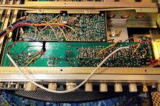
Though this receiver doesn't have pre-in / main-out jacks in the rear, I bypassed the preamp section on one channel with a cable (see photo) and the hiss went away in that channel. This is why I suspect that the noise is coming from the preamp.
There's a much more detailed post about this at Audiokarma but I'll summarize. I've done all the obvious: replaced all the electrolytic caps, replaced all the transistors and diodes in the signal path, recapped the power supply and replaced diodes, and thoroughly cleaned all the pots and switches with Deoxit. I've tried the freeze spray trick to no avail. All the solder joints look good. Voltages look good.
I'm hoping that someone here might be able to analyze the schematic (I'm still new at this) and suggest some other places to look.
I'm also wondering if it would make sense to modify the gain of the amplifier section so that the hiss will fall below the noise floor. As it stands this receiver has WAY too much gain for listening in my quiet room; I seldom turn the volume past the 7-8 o'clock position.
I have purchased a scope (that I'm still learning how to use) to aid in troubleshooting. Across an 8 ohm dummy load I see 15.5mV RMS of noise on the L channel.
I'm restoring a Sansui QRX-7001 receiver and have stumbled onto a stubborn problem with hiss, loud enough to be audible at the listening position. I believe it is coming from the preamp section (called the Tone Control board). It is in both channels at any volume level. The volume control is at the very front of the preamp section.
Though this receiver doesn't have pre-in / main-out jacks in the rear, I bypassed the preamp section on one channel with a cable (see photo) and the hiss went away in that channel. This is why I suspect that the noise is coming from the preamp.
There's a much more detailed post about this at Audiokarma but I'll summarize. I've done all the obvious: replaced all the electrolytic caps, replaced all the transistors and diodes in the signal path, recapped the power supply and replaced diodes, and thoroughly cleaned all the pots and switches with Deoxit. I've tried the freeze spray trick to no avail. All the solder joints look good. Voltages look good.
I'm hoping that someone here might be able to analyze the schematic (I'm still new at this) and suggest some other places to look.
I'm also wondering if it would make sense to modify the gain of the amplifier section so that the hiss will fall below the noise floor. As it stands this receiver has WAY too much gain for listening in my quiet room; I seldom turn the volume past the 7-8 o'clock position.
I have purchased a scope (that I'm still learning how to use) to aid in troubleshooting. Across an 8 ohm dummy load I see 15.5mV RMS of noise on the L channel.
Attachments
with what? usually one would use ksa992,ksc1845replaced all the transistors and diodes in the signal path,
Was the hiss there before your restoration work?
the hiss would increase significantly if the tone control (treble) is at its maximum
with what? usually one would use ksa992,ksc1845
Yes - those are the substitutes I used in the Tone Control board. There's a larger variety of transitors and diodes on the Driver Board that I replaced with different substitutes.
Was the hiss there before your restoration work?
No, I don't think so. There's always ear-next-to-the-tweeter hiss of course but this louder hiss started happening during my restoration. I cannot pinpoint exactly when it started to happen, but I think I first noticed it after I recapped the speaker protect relay board. That was around the same time I did the Tone Control board as well. And with the speaker protect relay board still in the circuit and the Tone Control board bypassed I don't hear the hiss. (I also replaced the relay with a new one just in case that was the culprit).
the hiss would increase significantly if the tone control (treble) is at its maximum
Yes, it does.
I should add that I have tried two sets of KSA992FTA and KSC1845FTA transitors on the Tone Control board already.
The first set I installed were purchased in small qty so I figured both to chase the hiss and to get better matching I'd try larger cut-tape quantities.
I measured the hFE with my DMM and found the KSC1845FTA's measured 323 and the KSA922FTA's measured 330. "The meter will show the approximate hFE value for the test condition of base current 10 µA DC and Vce 2.8 VDC".
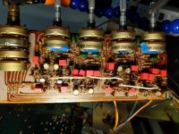
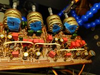
I've attached a couple of photos that show the board as it is now - the green mylar caps and all the resistors are original; the electrolytics and film caps are new.
The first set I installed were purchased in small qty so I figured both to chase the hiss and to get better matching I'd try larger cut-tape quantities.
I measured the hFE with my DMM and found the KSC1845FTA's measured 323 and the KSA922FTA's measured 330. "The meter will show the approximate hFE value for the test condition of base current 10 µA DC and Vce 2.8 VDC".
I've attached a couple of photos that show the board as it is now - the green mylar caps and all the resistors are original; the electrolytics and film caps are new.
Attachments
Last edited:
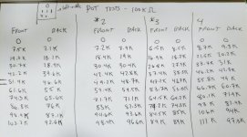
Do all the potentiometers measure ok, end to end and from each end to the wiper?
Yes - I've attached my notes from measuring each click stop of the Bass and Treble pots for the front and back channels. I also measured the balance and volume control pots and they looked good. The channel matching isn't perfect but they work. I have a thread on AK about the pots as well
") .
.Attachments
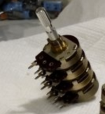
The configuration of the volume pots is unusual - three sections chained together. I think two of the sections are for preset controls? Certainly the last seems to be individual front/back level presets - setting these to maximum ought to prevent them adding noise.
The second section also seems to be a preset and should be set to maximum to prevent it adding noise.
Also they are 250k each section so the noise is going to be noticable in the best of worlds, that's pretty high, 50k would be much more normal, 10k would be great if the previous sections can drive it.
In particular having the presets at 50:50 resistance ratio puts upto 60k of noise resistance into the signal path, the worst configuration of all 3 pots would provide upto about 80k if I'm not mistaken. A single 50k pot can only put <=12.5k of effective noise into the path, a 10k pot <=2.5k
80k gives 5µV of voltage noise across 20kHz bandwidth, 2.5k only 0.9µV
With a normal power amp that's about 0.12mV and 20µV at the speaker terminals respectively. Might be worth considering different volume pot?
Last edited:
A little more information here. This is a quad receiver which is why you see 4 channels instead of just 2. I am getting hiss on all 4 channels as far as I can tell (I've tried the speakers in both front and rear positions).
As far as the configuration of the 3 250K pots they are Volume, Balance L-R and Balance Front-Back. I have them all set at center points.
Interestingly, when I adjust the balance knob from L channel to R channel, the hiss actually increases in the L channel. Not sure what that's about. This is a very complex receiver. I am using it as a 2-ch receiver and as such I have it set in 2-ch front direct mode (which comes after the Tone Control board) and I believe routes the audio signal only to the front driver board rather than both the front and rear driver boards.
The second section also seems to be a preset and should be set to maximum to prevent it adding noise.
I set the second section, which is Front/Back balance, all the way to Front only. Might hear a teeny tiny reduction in hiss but nothing dramatic. No reason not to have it set that way, though, since I'm not using the rear channels at the moment.
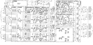
The full service manual w/ schematics is available at HiFi engine: Sansui QRX-7001 - Manual - 4-Channel Receiver - HiFi Engine. The segment I posted is a screenshot of but one of 4 sets of schematics for the receiver. I have many of the parts removed (including the Phono stage, the quad processing boards, the rear channel driver board, the FM tuner, etc.) as I have been working to isolate this issue to just the 2-channel front speaker signal path.
I'm sure the noise is a bit louder right now with all the covers off, etc., but I have tested it fully assembled with all the covers back in place and it's still an issue.
Last edited:
A little more information here. This is a quad receiver which is why you see 4 channels instead of just 2. I am getting hiss on all 4 channels as far as I can tell (I've tried the speakers in both front and rear positions).
As far as the configuration of the 3 250K pots they are Volume, Balance L-R and Balance Front-Back. I have them all set at center points.
Interestingly, when I adjust the balance knob from L channel to R channel, the hiss actually increases in the L channel. Not sure what that's about. This is a very complex receiver. I am using it as a 2-ch receiver and as such I have it set in 2-ch front direct mode (which comes after the Tone Control board) and I believe routes the audio signal only to the front driver board rather than both the front and rear driver boards.
Ah, I see - the taper is metal from one end to the centre, then carbon, for the balance pots - so centering should make all of them zero ohms straight-through, which is good. That explains the noise increasing on unbalancing them, since the channel being attenuated gets more series resistance and more noise, and confirms the pots are too high a value for decent noise performance (not saying nothing else is at fault, but they are definitely able to make a difference). With no input signal (input shorted), if you set the main volume to maximum, does the noise drop away? (Ditto for minimum volume setting)
With no input signal (input shorted), if you set the main volume to maximum, does the noise drop away? (Ditto for minimum volume setting)
I don't have shorting plugs (though I could potentially hack some together by sacrificing an RCA cable) but when I disengage the AUX input and unplug the cables no, the hiss doesn't go away at max or minimum main volume. It's louder with the main volume at maximum and about the same volume throughout the first 1/3 of the volume control range. At minimum it is still quite audible.
This receiver is from 1974 so I am sure it's a bit noisier than modern gear - the owner's manual lists the "Hum and Noise" on the AUX input as "Better than 80dB". I don't expect that I will hear zero hiss with my ear next to the tweeter but this is loud hiss audible from the listening position that has gotten worse after I started the restoration. Speakers are spec'ed at 90dB sensitivity.
On a completely different tack one cause of extra noise can be a DC current in the signal path - perhaps through the pots, especially if there's a carbon resistor involved that exhibits excess noise. A leaky capacitor is another possible culprit. But you have this on all channels which goes against this idea.
Very noisy supply rail is another suspect to consider.
Very noisy supply rail is another suspect to consider.
Its easy to short an RCA plug with a piece of wire temporarily, a pair of tweezers would serve even. Most amps are most noisy with input disconnected, so its important to short the inputs to test actual amp noise.
Hey, sorry, I appreciate your patience with me - never done that before!
I shorted the RCA inputs w/ some wire and observed the same result at minimum and maximum overall volume setting. Hiss doesn't drop out at either setting.
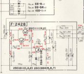
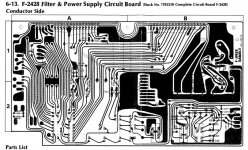
As far as the noisy DC rail - I've attached a screenshot of the power supply schematic for this board and another that shows my measured voltages. I highlighted the 38V rail out of the power supply and into the tone control board.
I've recapped the power supply board already but the transistors are still original. I don't have a replacement for the 2SC1211 but I do have replacements for the two smaller transistors and am going to try swapping those. I already swapped the rectifier diodes (highlighted) based on a suggestion from an AudioKarma user. Any tips for measuring noise on the DC rail?
Thanks again for all your time
.Attachments
Hmm, lots of caps on those supply rails, so recapped its got to be pretty quiet (assuming no dry joints or hairline track splits). You say bypassing the preamp fixed things, so I guess need to concetrate on the preamp sections - perhaps something is badly mis-biased in there, or a transistor in upside down (they don't work so well that way, but may work enough to confuse!) Its an interesting mystery so far, glad to throw some ideas in.
Oh, and there is always the high frequency oscillation issue to consider, often that produces audible noise without totally ruining the audio response.
Oh, and there is always the high frequency oscillation issue to consider, often that produces audible noise without totally ruining the audio response.
OP, what sensitivity are your speakers?
Had a quick look at the circuit.
There is a capacitor on the preamp board which does not appear in the schematic, C601, forming an RC filter for the +30V supply with R601. I hope you changed that, too.
Gains are ca. 14.8 dB for the preamp, 33.5 dB for the power amp. 48 dB is a tad on the high side for a 45wpc unit, where 42-43.5 dB would be more like it these days. Projected output noise comes out to roughly 300 µVrms - not exactly up to modern standards but certainly usable, and not a great deal worse than run of the mill '90s receivers. Still not what you want for above average sensitivity speakers though. The combination of both may be the issue.
Beware: 2SA726 and 2SC1313 seem to be some of the older types with BCE pinout, rather than ECB as most Japanese transistors are. Verify that all of their replacements are in the other way round.
Attenuator wise, I would suggest inserting an extra resistor R1 in series with the existing 3µ3 output coupling caps (note: never bend electrolytic cap legs directly at the part) and replacing the following 220ks to ground with R2. R1 = 47k, R2 = 10k seems worth a shot, that should be a decent compromise. It basically cancels preamp gain but with volume typically set to 7-8 o'clock now, that seems quite necessary.
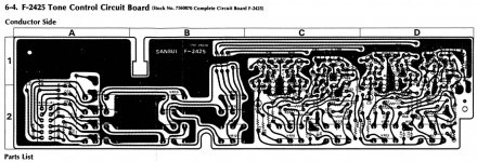
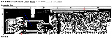
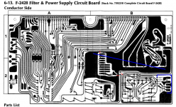
I spotted at least two ground loops on the F-2428 board, some modding action seems like a good idea there - I'd have to think about where to best place cuts and wires. F-2425 looks like it has similar issues but the traces are not that easy to make out in the service manual, and I'd really want a better picture / scan of the underside to be sure.
Had a quick look at the circuit.
There is a capacitor on the preamp board which does not appear in the schematic, C601, forming an RC filter for the +30V supply with R601. I hope you changed that, too.
Gains are ca. 14.8 dB for the preamp, 33.5 dB for the power amp. 48 dB is a tad on the high side for a 45wpc unit, where 42-43.5 dB would be more like it these days. Projected output noise comes out to roughly 300 µVrms - not exactly up to modern standards but certainly usable, and not a great deal worse than run of the mill '90s receivers. Still not what you want for above average sensitivity speakers though. The combination of both may be the issue.
Beware: 2SA726 and 2SC1313 seem to be some of the older types with BCE pinout, rather than ECB as most Japanese transistors are. Verify that all of their replacements are in the other way round.
Attenuator wise, I would suggest inserting an extra resistor R1 in series with the existing 3µ3 output coupling caps (note: never bend electrolytic cap legs directly at the part) and replacing the following 220ks to ground with R2. R1 = 47k, R2 = 10k seems worth a shot, that should be a decent compromise. It basically cancels preamp gain but with volume typically set to 7-8 o'clock now, that seems quite necessary.
I spotted at least two ground loops on the F-2428 board, some modding action seems like a good idea there - I'd have to think about where to best place cuts and wires. F-2425 looks like it has similar issues but the traces are not that easy to make out in the service manual, and I'd really want a better picture / scan of the underside to be sure.
Last edited:
Thank you for taking the time to analyze the schematic!
) and I sit about 6' away from them.
C601 was a 47uF 50V electrolytic; I replaced it with a Nichicon Fine Gold 47uF 80V. I kept all the capacitor values original, only substituting higher voltage caps in a few select spots. Given the amount of physical space on the board I could increase the capacitance here; what do you think?
Yes -- the modern replacements are ECB and I have double-checked that I installed them in the correct orientation, 180* from the originals.
I was able to find electrolytics with the same lead spacing as the originals so I didn't have to bend any legs directly at the part. I did use WIMA MKS2 film caps in place of the small-value electrolytics (1uF and 3.3uF) and in some cases I had to bend the legs a bit inward or outward on those. Possible problem? No major stress on the leads.
Thank you for the attenuation suggestion - this is just what I was looking for. I've attached a marked up schematic to verify that I'm understanding you correctly. Would appreciate if you could take a look and let me know if I've accurately captured your suggestion. The 220K resistors to ground that you speak of are R35-38 in the schematic, yes?
I have another copy of the service manual that might be a little clearer in terms of the layout of the copper traces on the PCB. I've attached screenshots in case that might be of help. I can of course share photos as well, though it's hard to get a photo of the underside of the F-2428 board in its entirety given the way it's situated in the receiver. There are also a ton of jumpers (factory) on it so the traces might be a bit confusing to interpret.
I made one small additional change last night: I replaced the two small transistors in the 38V power supply w/ modern replacements. No impact on the hiss. I'll be replacing the zener as well. The big TO-3 2SC1111 is original. Before I began this restoration I noticed it getting VERY hot (I think there may have been a short on one of the quad boards or the CD-4 module, which I have since removed - it no longer gets hot) so I might try replacing that one with a MJ15001G. That said, if modifying the gain of the preamp solves the hiss problem and the 2SC1111 no longer gets hot when I re-install the now-recapped quad boards I will leave well enough alone. Not trying to shotgun every single component in this receiver (just most of it).
Thanks again!
They are listed as 90dB (1W/1M) in the only docs I could find about them. I have them set up in a smallish, quiet, lightly dampened room (which is too messy right now for me to share a picOP, what sensitivity are your speakers?
) and I sit about 6' away from them. There is a capacitor on the preamp board which does not appear in the schematic, C601, forming an RC filter for the +30V supply with R601. I hope you changed that, too.
C601 was a 47uF 50V electrolytic; I replaced it with a Nichicon Fine Gold 47uF 80V. I kept all the capacitor values original, only substituting higher voltage caps in a few select spots. Given the amount of physical space on the board I could increase the capacitance here; what do you think?
Beware: 2SA726 and 2SC1313 seem to be some of the older types with BCE pinout, rather than ECB as most Japanese transistors are. Verify that all of their replacements are in the other way round.
Yes -- the modern replacements are ECB and I have double-checked that I installed them in the correct orientation, 180* from the originals.
Attenuator wise, I would suggest inserting an extra resistor R1 in series with the existing 3µ3 output coupling caps (note: never bend electrolytic cap legs directly at the part) and replacing the following 220ks to ground with R2. R1 = 47k, R2 = 10k seems worth a shot, that should be a decent compromise. It basically cancels preamp gain but with volume typically set to 7-8 o'clock now, that seems quite necessary.
I was able to find electrolytics with the same lead spacing as the originals so I didn't have to bend any legs directly at the part. I did use WIMA MKS2 film caps in place of the small-value electrolytics (1uF and 3.3uF) and in some cases I had to bend the legs a bit inward or outward on those. Possible problem? No major stress on the leads.
Thank you for the attenuation suggestion - this is just what I was looking for. I've attached a marked up schematic to verify that I'm understanding you correctly. Would appreciate if you could take a look and let me know if I've accurately captured your suggestion. The 220K resistors to ground that you speak of are R35-38 in the schematic, yes?
I spotted at least two ground loops on the F-2428 board, some modding action seems like a good idea there - I'd have to think about where to best place cuts and wires. F-2425 looks like it has similar issues but the traces are not that easy to make out in the service manual, and I'd really want a better picture / scan of the underside to be sure.
I have another copy of the service manual that might be a little clearer in terms of the layout of the copper traces on the PCB. I've attached screenshots in case that might be of help. I can of course share photos as well, though it's hard to get a photo of the underside of the F-2428 board in its entirety given the way it's situated in the receiver. There are also a ton of jumpers (factory) on it so the traces might be a bit confusing to interpret.
I made one small additional change last night: I replaced the two small transistors in the 38V power supply w/ modern replacements. No impact on the hiss. I'll be replacing the zener as well. The big TO-3 2SC1111 is original. Before I began this restoration I noticed it getting VERY hot (I think there may have been a short on one of the quad boards or the CD-4 module, which I have since removed - it no longer gets hot) so I might try replacing that one with a MJ15001G. That said, if modifying the gain of the preamp solves the hiss problem and the 2SC1111 no longer gets hot when I re-install the now-recapped quad boards I will leave well enough alone. Not trying to shotgun every single component in this receiver (just most of it
).Thanks again!
Attachments
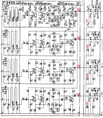
Looks good to me.Thank you for the attenuation suggestion - this is just what I was looking for. I've attached a marked up schematic to verify that I'm understanding you correctly. Would appreciate if you could take a look and let me know if I've accurately captured your suggestion. The 220K resistors to ground that you speak of are R35-38 in the schematic, yes?
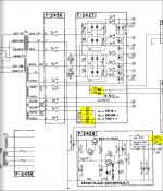
Here are my suggestions for the modification of the two boards. Red X or line = cut, blue = wire. Cuts can be sealed back up with clear nail polish or similar.
F-2425: I hope the two dots next to the narrow board section in quadrant B1 do not already indicate a wire link between the two sections, otherwise the wire would be redundant.
F-2428: Thinner blue wire (bottom right) to be routed right underneath the trace.
I wouldn't expect anything groundbreaking (no pun intended), otherwise they would have caught this in the factory. Maybe a bit less hum. 3 out of 4 loops have long thin sections to begin with. Sansuis were generally free from ground loops from about 1977 on.
Attachments
- Status
- This old topic is closed. If you want to reopen this topic, contact a moderator using the "Report Post" button.
- Home
- Amplifiers
- Solid State
- Eliminating hiss and maybe reducing gain on Sansui QRX-7001