I would like to build a preamplifier for an electrect mic, actually i've some WM61-A.
I would like to get SPL values.
My SPL measure could event be low accurancy (+-6db is accettable) even not weighted, and it should be at least from 40/50db to 90/100.
Micro side i'm using simple RMS, or radix-4 fft, depends on the signal precision and on how much resources i've got on micro.
Because i would like to post this project, i prefer NOT to do Linkwitz.
Said this, my electronics skills are not as good as my it skills, so i ask you expert if you've a working circuit, i've try some as you can see, but nothing as good as i need
zx-sound: http://www.inexglobal.com/downloads/ZX-sound_e.pdf
transistor pre: http://cdn.head-fi.org/b/bf/bfb6b58e_simplepreamp.gif
opamp pre: http://www.zen22142.zen.co.uk/Circuits/Audio/tl071_mic.png
Last edited:
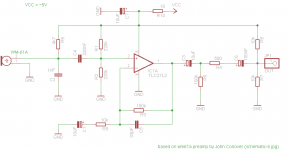
solved using a schematics base on this http://www.johncon.com/john/wm61a/graphics/schematic-6.jpg
see attached if interested
see attached if interested
Attachments
thank you.
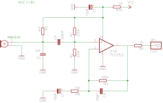
i add the decoupling cap C6 and biasing res R7 / R8, cause i need signal biased at 2.5v, (given 5v supply).
C3, R6, R4 i do not know what are there for they are there because john use those.
note that i need this circuit for a basic SPL meter, so i use john schematics even because i know the RMS voltage at a given SPL (es 315uV ~ 32db), and so if i get the RMS voltage i can calculate output SPL: SPL db = 20*log10(newRMSv/referenceRMSv).
i add the decoupling cap C6 and biasing res R7 / R8, cause i need signal biased at 2.5v, (given 5v supply).
C3, R6, R4 i do not know what are there for
note that i need this circuit for a basic SPL meter, so i use john schematics even because i know the RMS voltage at a given SPL (es 315uV ~ 32db), and so if i get the RMS voltage i can calculate output SPL: SPL db = 20*log10(newRMSv/referenceRMSv).
works perfect from ~55..100db SPL, better than before, it seems it has more dinamic on low SPL values.
attached the new schematic, R4 optional.
if you have time to reply me i've some more questions, otherway thanks for the above suggestion.
1) C5, C2, R10 are filters, right?
2) do you see any other improvement?
3) john write as the reference value 315uV ~32db SPL, is it this value take out from experimenting with AC coupled scope and emitting a sound @32db, or there is a way to calculate this value based on the IC, supply voltage, mic, and components used?
Attachments
1) All network is a filter any way, some are simpler and some too complex.
2) I have no experience in microphones, but the gain in the amplifier is the value of the resistor from output to -input(R3), divided by the value of -input to ground (R9) (Ignore the capacitor in series), plus 1. This case gain is 11.
3) Improvements, no, there are lots, but as Murphy says: any equipment working is untouchable.
Last edited:
- Status
- This old topic is closed. If you want to reopen this topic, contact a moderator using the "Report Post" button.
- Home
- Source & Line
- Analog Line Level
- electret mic preamp for micro ADC

