Hi guys,
Need some help on EL152 German datasheet. The EL152 has a 40W anode/plate dissipation. It is strange that (if I translate it correctly), on page 10, when triode-connected, the steady state current Iao is only 30mA?
Refer datasheet below:
http://www.mif.pg.gda.pl/homepages/frank/sheets/118/e/EL152.pdf
If it is a 40W plate, when triode connected with the anode voltage at 400V, by right the maximum anode current should be able to go up to 100mA.
I tried to refer else, for example, in page 9 of datasheet, in pentode mode, it states 300V on anode/plate but the Ia is left empty. Issh...
I'm scratching my head all over. Hope the gurus here could give me some advice or explanation on the above.
Thanks!
Need some help on EL152 German datasheet. The EL152 has a 40W anode/plate dissipation. It is strange that (if I translate it correctly), on page 10, when triode-connected, the steady state current Iao is only 30mA?
Refer datasheet below:
http://www.mif.pg.gda.pl/homepages/frank/sheets/118/e/EL152.pdf
If it is a 40W plate, when triode connected with the anode voltage at 400V, by right the maximum anode current should be able to go up to 100mA.
I tried to refer else, for example, in page 9 of datasheet, in pentode mode, it states 300V on anode/plate but the Ia is left empty. Issh...
I'm scratching my head all over.
Hope the gurus here could give me some advice or explanation on the above. Thanks!
Indeed somewhat curious data,you don't expect from the German "grundlichkeit".
I supose you may go for 400V/60mA ,don't think you get even 5W out.
Why 60mA? Pg2=5Wmax that is 12.5mA at 400V.Safeside say 10mA.The other data indicate that Ig2 is aprox.20% of Ia.Gives Ia=50mA+10mA(g2) total of 60mA.
Mona
I supose you may go for 400V/60mA ,don't think you get even 5W out.
Why 60mA? Pg2=5Wmax that is 12.5mA at 400V.Safeside say 10mA.The other data indicate that Ig2 is aprox.20% of Ia.Gives Ia=50mA+10mA(g2) total of 60mA.
Mona
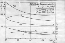
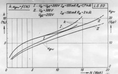
I assume that you want to use the EL152 in SE Triode mode. The EL152 as well the GU50 is basically a copy of the RF/AF power pentode LS50. Here are some data for that tube in SE Triode mode. You will find the output power for 250V and 400V as a parameter of the OT impedance. In that diagram Iad is the plate current at full power.
Attachments
Shoog/Ketje,
Man... I thought with 40W Pa, I can get something decent out of it. Looks like it's a bummer. I need to research more on how to dig out more power from this tube. I have not seen any successful implementation of this tube in the internet yet.
es345,
Thanks! Do you have any recommendations on the operating point for EL152?
Thanks guys!
Man... I thought with 40W Pa, I can get something decent out of it. Looks like it's a bummer.
I need to research more on how to dig out more power from this tube. I have not seen any successful implementation of this tube in the internet yet. es345,
Thanks! Do you have any recommendations on the operating point for EL152?
Thanks guys!
You could try a pentode implementation with plate to grid feedback. This should allow you to respect the g2 voltage whilst running at your higher plate current. It should allow you to produce something very similar or better than Triode performance with lower output impedance than a straight triode configuration.
If you do - make certain to use a pentode driver.
Also it seems that a GU50 schematic might easily be adapted.
Shoog
If you do - make certain to use a pentode driver.
Also it seems that a GU50 schematic might easily be adapted.
Shoog
Last edited:
Thanks! Do you have any recommendations on the operating point for EL152?
Well, I personally don't use them in SE Mode but in PPP. My 6xGu50 bass amp is working in class B producing about 400W Output (Raa 2KOhm)
I had a similar concern with a GU50 triode strapped, but more related to how much voltage the g2 could take (specified with 250V max). I performed some measurements at 500V anode/g2 showing that g2 current in triode mode is basically negligible - g2 dissipation is definetly not an issue. This seems logical considering the significantly larger anode surface that simply attracts way more electrons then a grid-wire at the same potential. G2 is usually "at risk" when it has to take over the current of the anode, e.g. in UL or penthode operation where the anode voltage can swing much lower then g2 potential. But since both anode and g2 are tied together, they share the same potential at any time.
Bottom line, here it works with 500V and 60mA - might be luck, don't know... One thing to notice thought is that Rg1 is supposed to be low for LS/GU50/EL152. Specification talks 25k'ish which requires a beefy driver. Maybe the 30mA spec limit is in place to prevent from thermal runaway issues (which I have not seen so far)?
Marcus
es345,
That's a lot of power! I'm basically looking at maybe 15W for my applications. I'm running it with Zu Soul Superfly that is pretty high in efficiency despite not being a single full range driver (close enough). Thanks for the curve!
Marcus,
I've seen quite a number of GU50 schematics online disregarding the G2 voltage in triode mode where they just simply connect the G2 to the anode. Haven't heard any disaster stories yet.
es345,
Marcus,
I've seen quite a number of GU50 schematics online disregarding the G2 voltage in triode mode where they just simply connect the G2 to the anode. Haven't heard any disaster stories yet.
Found this in the meantime:
FORUM - Maximale Ua bei Pseudo-Triode
The copy is aparently taken from a Telefunken LS50 lab report: see 2. for operating points triode strapped. Never made it into the released specification though.
Marcus
this tube is not exactly steep, it need high voltages to be happy.
German "k" (klirrfaktor) = thd,
"D" (Durchgriff) = 1 divided by the amplificationfactor
"Spezialtriodenschaltung" is zero-bias B2, it is only used when very high power and efficiency is wanted, for example a pair of 807 driven with 10W on the grids can give 120W output, so I can imagine a pair of EL152 should easely give 200W
Last edited:
I have seen curves fo the LS50 as quasitriode with voltages in excess of 1kV on a/g2
(can not remember was it up to 1,2 or 1,5kV)
Tied to anode it can swing up to 1000V or more, but it does not mean you can use it in triode mode with 1KV B+ -- you will get very non-linear result.
In "right-handed" triode all grids are tied together.
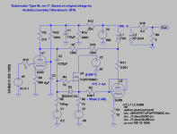
Here is the one that I like: Author is Frank "Knarf" from wavebourn.com forum
Attachments
- Status
- This old topic is closed. If you want to reopen this topic, contact a moderator using the "Report Post" button.
- Home
- Amplifiers
- Tubes / Valves
- EL152 maximum operating settings?