I have two of these built with kits from E-bay.
Running from an 18-0-18 transformer.
Voltage adjustment works well across the range.
The problem is that with the output set for + - 24v
the heatsinks are reaching 100C!
Anyone had any experience , or ideas with this kit?
With that heat I do not feel happy enclosing it in a pre-amp chassis.
Class A Parallel Adjustable Regulated Power Supply DIY Kits output +-5V ~ +-20V | eBay
Attachments
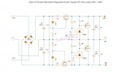
It is a symmetrical voltage regulator based on current source circuits (the BD140/BD139 to the left) followed by shunt-regulators (the BD140/BD139 to the right). The maximum output current is close to 100mA (depends on the LED forward voltage).
With 18-0-18Vac at the input, the rectified voltage may even exceed the voltage rating of the 2200uF/25V input capacitors (they have a hard life).
The power loss in the current sources BD140/BD139 is close to 2W for each at +/-5V output. The power loss in the shunt regulators BD140/BD139 is close to 1.5W for each at +/-15V output. That type of small heatsinks (I use them myself) are not as efficient as they look because the air-flow is hampered by the PCB.
Shunt regulators are characterized by that even at zero load current, the power losses in the regulator circuit exceed the maximum output power. It is not like for series regulators.
What are you going to use the boards for? What output voltage do you need? What is the maximum output current you need?
Last edited:
Shunt regulators are, opposite to series regulators, not general purpose voltage regulators but typically designed for a specific use.
Out of interest, what would be a typical use for a shunt regulator?
Out of interest, what would be a typical use for a shunt regulator?
As "Katie" (or her dad) writes, shunt regulators can be designed for very good noise performance and very fast load step response. I guess most are used in delicate measuring designs.
The design procedure (in short) is to determine the load voltage and in particular the absolute maximum and absolute minimum load current. Design a current source (eventually just a simple power resistor) that always delivers a little more current than the absolute maximum load current, Finding a power source that ensures the current source will function well (also worst-case) but with a moderate power loss (no excessive voltage). Design a shunt-regulator with good dynamic performance that power-wise can handle the current source current minus the absolute minimum load current. In principle a straight forward design method but with a load having importantly varying consumption, you soon understand the power loss that is inherent with that type of design.
Hence, for that type of voltage regulators you design around the load characteristics. You do generally not just do as with series regulators, make a general voltage regulator and let the user find an application.
Last edited:
The intention was to use this as a low noise supply for a BA3 pre-amp.
If you can tell me the operational voltage, the absolute maximum current consumption and the absolute minimum current consumption of a BA3 pre-amp, we can adapt the regulator design.
- Status
- This old topic is closed. If you want to reopen this topic, contact a moderator using the "Report Post" button.
- Home
- Amplifiers
- Power Supplies
- E-bay power supply running hot.