For stereo amps a single star ground was what I have used with good results. Now I am drilling the chasis for a dual mono amp. I am struggling with the choice of a single star ground or 2 separate star grounds to provide better isolation and minimum hum. I use 2 bridge rectifiers per Tx therefore the centre taps are not grounded.
Here is my plan: ring terminators and solder lugs are tied to (a) 4mm screw(s) connected to the chasis in the following order from top to bottom:
Star Ground One (Left Channel):
1. Common ground
2. Zobel ground
3. PCB rail decoupling ground
4. PSU ground
5. Speaker negative return ground
6. Earth
7. RAC / interconnect shield
8. Speaker shield (Cobra Shielded Speaker cable)
9. Chasis
Star Ground Two (Right Channel):
Same as above.
I thought 2 star grounds are preferrable to the single star ground like the one below:
1. Common ground (left)
2. Common ground (right)
3. Zobel ground (left)
4. Zobel ground (right)
5. PCB rail decoupling ground (left)
6. PCB rail decoupling ground (right)
7. PSU ground (left)
8. PSU ground (right)
9. Speaker negative return ground (left)
10. Speaker negative return ground (right)
11. Earth
12. RAC / interconnect shield (left)
13. RAC / interconnect shield (right)
14. Speaker shield (Cobra Shielded Speaker cable) (left)
15. Speaker shield (Cobra Shielded Speaker cable) (right)
16. Chasis
I guess the separate star grounds would enable large current returns from the speakers to return to the correct PSU and not to have much effects on the other channel. The Earth is branched out from the AC power socket. The chasis connects the two star grounds together. I do hope this does not introduce any ground loops because if the 2 star grounds are placed close to each other (up to 100mm apart) there should not be much potential between the 2 points.
Do you think they will work? Any better ideas, better topologies or grounding schemes?
Many thanks.
Regards,
Bill
Hi,
I would go for one star ground.
However I would separate the earth and chassis from the star.
If you decide to keep all the grounds together then move the safety earth down the bolt to the chassis and use it's own nut to permanently trap it there.
Try having the star floating with respect to the earth+chassis.
You can then try a resistor and or capacitor coupling between star ground and safety earth or even a direct wire link (all grounds back together again).
The decoupling need very low inductance to operate at the high frequencies that require to be attenuated. This demands very short wires from star to decoupling ground. Put some thought into how you can achieve this. This may be what changes the requirement from one star to two star grounds, simply to give short wires to each board. Two grounds would be what are inside separated monoblocks so it does work.
Andrew,
Thanks for your help.
I have tried in my stereo amps floating the star by adding a resistor and a capacitor but it did not appear to have any difference. If I experience ground loops then I will most definitely use that again.
The picture below illustrates the my original plan for the layout of the dual mono amp using 2 stars. Note that the picture is not complete as some wires are missing. The black wires are the ground wires. I will use very THICK wires for decoupling. Nevertheless, with the layout some wires are not short. Would that be a problem?
Regards,
Bill
An externally hosted image should be here but it was not working when we last tested it.
Hi Bill,
having a bit of trouble deciphering your diagram.
It looks like you have the mains safety earth going to both star grounds?
Take your mains safety earth direct to chassis on a permanent bolted fixing. You can then run a connection to the star grounds with a wire or resistor depending on which you decide.
The second thing is it appears that you are running the capacitor commons to the star earth? This introduces large pulse currents and voltages onto your star ground. It then becomes a dirty ground, not what you want.
Instead, couple the capacitor commons together for each bank. Then run a connection to the respective star ground.
I cannot see the transformer centre taps? Connect these to the cap commons for the respective channels.
Do you need any more advice?
....hm, I always use two stars...
But not one left, and another right....
My first star is the PSU star (transformer, rectifier, heavy E-caps, may be also earth and enclosure) and the second star is the signal star.
PSU star and signal star are connected with one single wire of sufficient gauge.
My reason for this is that I discovered some noise in an amp with heavy PSU. The enormous cap charging current peaks can cause some
µVs voltage drop within the star ground connection that carries these currents. The amp correctly amplified this "signals" and produced 4mV peaks every 10ms at its output......
Hi ChocoHolic,
I absolutely agree, but I cannot get the message across because some have been lucky and avoided noise on the signal ground and then they recommend to keep all grounds together.
Keep the BIG currents away from the signal ground and interconnect the different grounds with single wire and/or resistors.
ChocoHolic said:
PSU star and signal star are connected with one single wire of sufficient gauge.
AndrewT said:
Keep the BIG currents away from the signal ground and interconnect the different grounds with single wire and/or resistors.
Thank you for those two posts, you both mentioned that the interconnection of the two star points 'power and signal' should be a sufficient wire guage. Would this be the awg of the signal wire to trace back to the power star or the opposite use power awg guage. Or does it not matter.
Its amazing you should see my 'misc grounding techniques file' for this and you two guys just cut out all the fat and simplified the explanation.
Stan
AndrewT said:Hi,
the only ground wire that needs to be bigger than 24awg is the interconnect from PSU common to power ground.
Remember to take ALL your speaker returns and decoupling caps and Thiel(Zobel) networks direct to the power ground.
Great! thank you...
Thanks Andrew and ChocoHolic. Sorry for getting back to this late because I did not have internet connection over the weekend.
So does the following layout make more sense?
The changes are:
(1) One aluminimum flat is used as the PSU common.
(2) Speaker negative wires go directly to the PSU common (and the Zobel).
(3) Earth is connected directly to the chasis below the power socket.
(4) Single wire from PSU common connects to the star which is connected to the circuit common, interconnect shields and the chasis.
Since 2 bridge rectifiers are used so the centre taps of the transformers are not connected to the PSU common.
With both PSUs in the monoblocks sharing the same aluminium flat would it introduce more cross-talks? What about the circuit commons share the same star?
Regards,
Bill
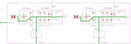
An externally hosted image should be here but it was not working when we last tested it.
Seems to be reasonable for me.
There is still room for detail discussions, but more
detailed analysis is difficult for me as long as I do not
sit myself in front of the particular amp.
Cross talk due to the shared aluminium flat should be uncritical.
...(as long as you don't need more than 90dB chanel separation)...
Good luck
Markus
Disclaimer:
.... you never know....")
There is still room for detail discussions, but more
detailed analysis is difficult for me as long as I do not
sit myself in front of the particular amp.
Cross talk due to the shared aluminium flat should be uncritical.
...(as long as you don't need more than 90dB chanel separation)...
Good luck
Markus
Disclaimer:
.... you never know....
Hi,
the only ground wire that needs to be bigger than 24awg is the interconnect from PSU common to power ground.
Remember to take ALL your speaker returns and decoupling caps and Thiel(Zobel) networks direct to the power ground.
AndrewT, can you comment on this? Shouldn't the zobel ground go to the same star point as the speaker and signal grounds, rather than the power ground? The power ground is the dirty one, and since the zobel is connected on the other end to the output of the amp, it is thus RC-coupled to the negative feedback of the amp. My thought is that this could inject noise if the ground reference of the zobel is not the same as signal ground.
the dual polarity PSU has three terminals:
+ve supply
-ve supply
Zero Volts
You take three wires from the PSU to the Amplifier PCB.
On the Amplifier PCB you have three power terminals:
+ve supply, -ve supply and Power Ground.
The Zobel does not pass Audio Signals.
The usual frequency roll-off (F-3dB) is >100kHz and often around 200kHz.
These HF currents need to be returned to the low impedance of the Power ground as close the the decoupling ground as you can get them.
What surprises me is that I was talking about this over 12 years ago and still many Builders take their reference back to the PSU smoothing capacitors where the charging current pulses dominate.
Last edited:
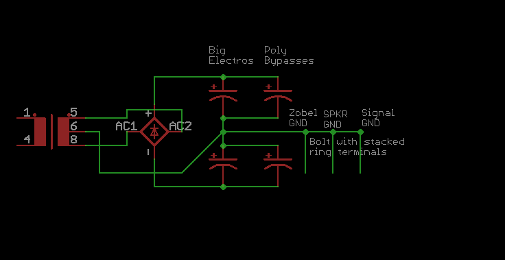
Here's the Eagle Schematic file if you want to illustrate any changes you would do.
Dropbox - Power Supply grouding illustration.sch
Dropbox - Power Supply grouding illustration.sch
and thus the Zobel currents must retyrun to the source in this case the output transistors.............. the currents through the zobel come directly from the output transistors,
no. The Zobel has to use the lowest impedance route back to the source of the current. That lowest impedance route is via the HF+MF decoupling ground through the HF & MF decoupling capacitors to the output devices.so I would think the return currents are wanting to return to the same place as the speaker and input references.
The HF+MF decoupling ground is the Power Ground of the amplifier.
Then analyse the route the speaker current takes from the output devices.
this drawing does not use best practice.I think we might be talking about the same thing. Do you agree with this diagram?
Have you installed household heating radiators?
Best is to use TBOE (stands for Top and Bottom Opposite Ends), i.e. the input and output at the radiator are diagonally opposite each other. This gives best heat flow and heat emission. But many installers use Bottom connections only because it saves work and pipe and it looks better to have short pipes coming up from the floor or through the wall. Most users will not realise that the "quickie" is sub-standard.
That analogy can be applied to electrical systems.
Look at your 2 groups of 2 capacitors.
Adopt TBOE.
The supply comes in at the top of the first and the return comes in at the bottom of the last.
Last edited:
For some peculiar reason almost everyone who chooses to use a 'star' ground also chooses to place this directly on the chassis. This almost invariably gives a low impedance connection from the 'star' to the chassis (which is not necessary) while ensuring that all other connections to the 'star' are higher impedance (which in some cases is undesirable). Why not put the 'star' where it will do most good, then run a single wire from there to the chassis.
The purpose of the Zobel is to ensure that the amp output does not see a significant capacitive load at high frequencies. It basically isolates/bypasses the speaker plus cable. Hence it should be connected across speaker+cable. It doesn't matter too much where you do this; low inductance is not a requirement.
The purpose of the Zobel is to ensure that the amp output does not see a significant capacitive load at high frequencies. It basically isolates/bypasses the speaker plus cable. Hence it should be connected across speaker+cable. It doesn't matter too much where you do this; low inductance is not a requirement.
- Status
- This old topic is closed. If you want to reopen this topic, contact a moderator using the "Report Post" button.
- Home
- Amplifiers
- Solid State
- Dual mono amp star grounding questions