I have heard this is suppose to be good, doesnt take long to bread board it and try
http://www.freeinfosociety.com/electronics/schemview.php?id=325
www.tonepad.com have some stuff as well
Dave
http://www.freeinfosociety.com/electronics/schemview.php?id=325
www.tonepad.com have some stuff as well
Dave
the hex inverter fuzz...... actually i find a TL072 more flexible and stable. also, the problem i see using a CMOS chip for a fuzz is a reliability issue. static electricity, just from plugging the cable into a guitar (all it takes is a measly 250V charge) to turn the hex inverter into a "never" gate, or a "pop amp".... bipolar and jfet inputs are a lot more forgiving of static discharge.if you can feel a static discharge on your fingertip, you're already up to about 5kV, so a charge that would damage the input of the CMOS chip might never be noticed, and suddenly the fuzz box no longer works.
I agree with unclejed613, however there are several ways around this static problem such as using clamping diodes, or even better using a simple capacitor coupled pre-amp before the cmos stage (transistor, op amp etc...) there are ways around it, best is try breadboard the circuit and try it out for your self. good luck.
Dave
Dave
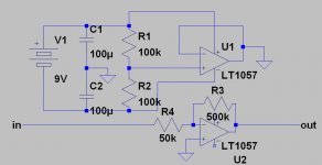
the following is what i use often as an onboard preamp. i usually use a TL062, not the LT part. if you want variable gain, use a pot for R3. the first half of the op amp is used as a "rail splitter" to provide a +/-4.5V supply from a standard 9V battery. the same principal can be used with a quad op amp, leaving 3 active sections available for preamp, tone control, etc...
Attachments
Have you checked out the designs available at http://www.runoffgroove.com/articles.html ???
- Status
- This old topic is closed. If you want to reopen this topic, contact a moderator using the "Report Post" button.
- Home
- Live Sound
- Instruments and Amps
- does someone have a good cmos overdrive schematic ???