Has anyone ever heared of Melody Amps /the SP9 model from them?
I found the SP9 model on the old manufacturers' website on webarchive: Page Title but couldn't find much information about the circuit. 6moons also has a review of the amp if somebody is interested: 6moons audio reviews: Melody Valve HiFi CD-M20 & SP9 I am asking because a friend of mine has bought one from sb who wanted to get rid of it for basically nothing and is taking it with him to my place somewhen in the winter holidays, so we can have a look at it together and maybe improve upon the circuit a little bit because despite it's supposedly decent build quality it was still made in China and they presumably cut costs in the wrong places. Neither one of us expects wonders from this amp but maybe we can get it to sound decent enough for a third system or maybe we'll just have fun and mess arround with the amp and see where it goes.
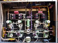
I'll post some pics he has taken from the inside of the SP9 later on.
If anyone knows anything about this amp or where I could get the schematic/service-manual for the SP9 please tell me where to look or whom I could call/write. Thanks.
I found the SP9 model on the old manufacturers' website on webarchive: Page Title but couldn't find much information about the circuit. 6moons also has a review of the amp if somebody is interested: 6moons audio reviews: Melody Valve HiFi CD-M20 & SP9 I am asking because a friend of mine has bought one from sb who wanted to get rid of it for basically nothing and is taking it with him to my place somewhen in the winter holidays, so we can have a look at it together and maybe improve upon the circuit a little bit because despite it's supposedly decent build quality it was still made in China and they presumably cut costs in the wrong places. Neither one of us expects wonders from this amp but maybe we can get it to sound decent enough for a third system or maybe we'll just have fun and mess arround with the amp and see where it goes.
I'll post some pics he has taken from the inside of the SP9 later on.
If anyone knows anything about this amp or where I could get the schematic/service-manual for the SP9 please tell me where to look or whom I could call/write. Thanks.
Last edited:
6moons points out what could be a significant shortcoming. A single 250 mA. 5AR4 is being asked to feed a KT88 class stereoblock. A Dyna MK3 uses a single 5AR4 for a KT88 monoblock.
Could be...any reccomendations for full-wave tube rectifier alternatives that I should consider (no matter if they use the same or a different socket) that have a similar warm-up of min. 15-20sec -so no directly heated rectifiers-?
The capability of the power transformer enters the picture. Working into a choke I/P filter, 350 mA. can be drawn from a GZ37. That type has a 3 A. heater, as opposed to the 2 A. heater in a 5AR4/GZ34, and you'd have to find a way to make up for the rail voltage reduction. Even 350 mA. could easily be inadequate.
I strongly suspect that more attention was paid to cosmetic considerations than Physics, when that amp was designed. If, very big if, the power trafo is truly competent, I suggest switching to Schottky diode rectified B+ and doing whatever is necessary to slow B+ rail rise. Both of the revered H/K Cit. 2 and "Mac" MC275 KT88 stereoblocks employ SS rectified B+. Adequate current handling from vacuum rectifiers is problematic, when 4X KT88s, along with small signal circuitry, require feeding. Maybe a pair of 6CJ3 damper diodes could do the job, but you have to find the requisite 3.6 A. of 6.3 VAC heater power.
I strongly suspect that more attention was paid to cosmetic considerations than Physics, when that amp was designed. If, very big if, the power trafo is truly competent, I suggest switching to Schottky diode rectified B+ and doing whatever is necessary to slow B+ rail rise. Both of the revered H/K Cit. 2 and "Mac" MC275 KT88 stereoblocks employ SS rectified B+. Adequate current handling from vacuum rectifiers is problematic, when 4X KT88s, along with small signal circuitry, require feeding. Maybe a pair of 6CJ3 damper diodes could do the job, but you have to find the requisite 3.6 A. of 6.3 VAC heater power.
Do *not* believe the claims of slower-than-the-signal-valves warmup for type GZ34 or (especially) type GZ37. The original ones anyway, and current GZ34s are caca. You must design for full unloaded voltage survivability.
Jan D. of _Linear Audio_ fame is introducing a delayed B+ device if you're worried about cold start of the signal valves. Folks will still argue about this after we're all dead and gone.
All good fortune,
Chris
Jan D. of _Linear Audio_ fame is introducing a delayed B+ device if you're worried about cold start of the signal valves. Folks will still argue about this after we're all dead and gone.
All good fortune,
Chris
Well, I guess I have to draw up one mayself then...
A job for an hour max.
The big improvements that can be made to these amps involves tossing the power transformer and output transformers, then adjusting the circuit design accordingly. Due to the cost of doing that, scratch building is really a wiser course of action.
Looking at the inside of the build, that amp looks to be cathode biased, which is highly unusual to say the least. I also see that the output tubes are tetrode wired. I thought this was really strange, but the KT88 datasheet does list a tetrode operating point with cathode bias that makes 50W, so perhaps it's not all that strange.
If you brought this amp to me to look over, I would start with a bench test to see how much power it's actually making, as well as how much power it can make down low. If that amp makes 50WPC and has a damping factor that's greater than 2, you have won the Chinese amp lottery and can probably leave it alone and be happy with what you have.
What I suspect, however, is that the damping factor will be closer to 1 and the output power more like 30W. It is under these conditions that you would want to consider tossing the output transformers (higher quality OPTs will not produce instabilities when adequate feedback is used) and altering the circuit to bring the amp's performance more in line with expectations. Triode strapping the finals is also an option, but the output transformer is likely 10K:8, which is too much of a step-down for a triode wired KT88.
If you cannot get some baseline measurements on what the amp is doing now, then finding someone to help you do that or obtaining the tools to do so would be paramount.
- Status
- This old topic is closed. If you want to reopen this topic, contact a moderator using the "Report Post" button.
- Home
- Amplifiers
- Tubes / Valves
- Does anyone know of the Melody SP9 amp?