Hi everyone,
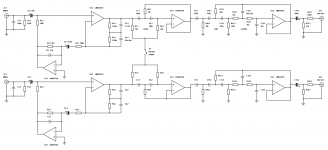
I thought I'd share a circuit that I am currently developing to sell as a PCB. It's a high quality RIAA phonostage with an 'electronically cooled' input stage, and also features a rather interesting and unique topology to filter out the antiphase rumble that resides in the stereo difference.
Gain 40dB @ 1kHz
Vertical rumble cut-off 146Hz
Lateral rumble cut-off 14Hz
Supersonic filter 42.5kHz
Attachments
How does the 'electronic cooling' work?
Being inherently inductive, the output impedance of any coil based phono cartridge increases with frequency. This presents a challenge, because as the impedance of the cartridge increases the load resistor (usually 47k) will contribute more thermal noise to the input stage at higher frequencies. This can increase the effective noise at the input by up to 6dB within the audio band.
To get around this problem, it is possible to simulate, using a higher value resistor and an inverting amplifier, a more ideal resistor that contributes significantly less thermal noise, hence 'electronic cooling'.
U1.1 acts as an inverting amplifier with a gain of approximately 27dB, being driven by the RIAA stage (U1.2). As the bottom end of loading resistor R2.1 is tied to this inverting amplifier, as opposed to ground, it's effective resistance becomes 52k17, much lower than 1M2. This combines with R1.1 to create an input impedance of 47k.
This results in a load resistance which contributes much less thermal noise, hence 'electronic cooling'.
Can you support your statement with any calculations, measurements? Looks like snake oil to me.This results in a load resistance which contributes much less thermal noise, hence 'electronic cooling'.
Consider the noise voltage generated by a normal 47k resistor that would be present at the input. This would be approximately 0.9uV with a bandwidth of 1kHz. This is created with a series resistance of 47k, of course.
Now consider the noise voltage generated by a 1M2 resistor, which is 4.4uV, this is much greater, but is presented through a much larger series resistance of 1M2.
So say that we are placing this 1kHz or so in between 9 and 10kHz. If a cartridge has an inductance of 400mH, then it's impedance in this range will be roughly 24k, much higher than it's effective series resistance. So we essentially (very roughly speaking) have a potential divider between the thermal noise voltage, the loading resistor, and the cartridge.
Now, with the 47k resistor at the top of the voltage divider we get a noise voltage of 0.3uV between 9 and 10kHz, but with the 1M2 resistor we get 0.086uV, a very substantial improvement of over 11dB.
By inverting and amplifying the signal present at the top of the 1M2 resistor and then presenting it at the bottom, we can decrease it's effective impedance down to about 50k or so, thus simulating a 50k resistor that is only capable of generating the noise current of a 1M2 resistor.
Not the best explanation, but I hope you get the jist of my point .
.
Now consider the noise voltage generated by a 1M2 resistor, which is 4.4uV, this is much greater, but is presented through a much larger series resistance of 1M2.
So say that we are placing this 1kHz or so in between 9 and 10kHz. If a cartridge has an inductance of 400mH, then it's impedance in this range will be roughly 24k, much higher than it's effective series resistance. So we essentially (very roughly speaking) have a potential divider between the thermal noise voltage, the loading resistor, and the cartridge.
Now, with the 47k resistor at the top of the voltage divider we get a noise voltage of 0.3uV between 9 and 10kHz, but with the 1M2 resistor we get 0.086uV, a very substantial improvement of over 11dB.
By inverting and amplifying the signal present at the top of the 1M2 resistor and then presenting it at the bottom, we can decrease it's effective impedance down to about 50k or so, thus simulating a 50k resistor that is only capable of generating the noise current of a 1M2 resistor.
Not the best explanation, but I hope you get the jist of my point
.
Can you support your statement with any calculations, measurements? Looks like snake oil to me.
To say the least not new, done with valves even. But seriously didn't Bob Cordell cover this in a thread here?
W. S. Percival, “An electrically ‘cold’ resistance,” Wireless Engineering,
vol. 16, pp. 237–240, May 1939
Last edited:
If you have an inductive source impedance (like an MM cartridge), then you can realise a significant improvement in noise performance by using a 'cold resistance' as you put it, to provide the loading.
I'm not claiming it as a new idea, but what I am saying is that it's a perfectly good use of a spare op-amp and a few pennies worth of resistors .
From my measurements, the impedance of most MM cartridges is much greater (5 times greater than the DC resistance even at 1kHz) than most people seem to realise in terms of inductance, meaning that the loading resistor contributes a very significant amount of noise, so as to warrant electronically cooled loading.
However, I feel that the most important feature of this phono-stage is the vertical canceling rumble filter. When phonograph discs are cut, the bass in the stereo difference must be sharply rolled off below 200Hz or so, to prevent excessive vertical excursion (the results of which can lead to the groove simply disappearing in the worst cases). In addition to this, most of the rumble above 20Hz lies in the vertical plane (stereo difference) of the stylus's motion, meaning that a differential high pass filter at 150Hz will bring great improvements to sound quality, intermodulation in loudspeakers, while not doing any damage to musical material and almost completely eliminating that 'road noise' sound that seems to be so inherent on vinyl.
To say the least not new, done with valves even.
I'm not claiming it as a new idea, but what I am saying is that it's a perfectly good use of a spare op-amp and a few pennies worth of resistors
.From my measurements, the impedance of most MM cartridges is much greater (5 times greater than the DC resistance even at 1kHz) than most people seem to realise in terms of inductance, meaning that the loading resistor contributes a very significant amount of noise, so as to warrant electronically cooled loading.
However, I feel that the most important feature of this phono-stage is the vertical canceling rumble filter. When phonograph discs are cut, the bass in the stereo difference must be sharply rolled off below 200Hz or so, to prevent excessive vertical excursion (the results of which can lead to the groove simply disappearing in the worst cases). In addition to this, most of the rumble above 20Hz lies in the vertical plane (stereo difference) of the stylus's motion, meaning that a differential high pass filter at 150Hz will bring great improvements to sound quality, intermodulation in loudspeakers, while not doing any damage to musical material and almost completely eliminating that 'road noise' sound that seems to be so inherent on vinyl.

Hans,
Thanks for the graph . I would be interesting to see some more, especially regarding the vertical filter (i.e. stereo difference response).
Read my previous comments in regard to 'electronic cooling'.
The idea is that the cartridge has an almost purely inductive impedance, so most of the noise comes from the loading resistor. By 'simulating' a 50k resistor using an active circuit, the noise contribution is greatly reduced.
Thanks for the graph
. I would be interesting to see some more, especially regarding the vertical filter (i.e. stereo difference response).Read my previous comments in regard to 'electronic cooling'.
The idea is that the cartridge has an almost purely inductive impedance, so most of the noise comes from the loading resistor. By 'simulating' a 50k resistor using an active circuit, the noise contribution is greatly reduced.
This is wrong. You must analyze the whole network which the input sees. The circuit consists of L+R1//R2//C where the R1 is the internal resistance of the cartridge and R2 your input load.Consider the noise voltage generated by a normal 47k resistor that would be present at the input. This would be approximately 0.9uV with a bandwidth of 1kHz. ...
Some good reading about noise
http://www.ti.com/lit/an/snva515c/snva515c.pdf
Last edited:
Read the second paragraph of that post, I know it's not perfect, but it shows the general idea.
Essentially you are limiting the effective noise current by increasing the value of the resistor, and then actively decreasing it's perceived resistance to ground with an inverting gain stage.
It is a little more complicated than that, what with reactive and resistive loads combining a little differently, but the rough idea still stands. the resistance of the cartridge itself is also fairly negligible.
Why not try simulating it yourself, and see what I mean if you are not convinced about the validity of this idea. A good model for a cartridge is a 600R resistor in series with a 400-500mH inductor.
So say that we are placing this 1kHz or so in between 9 and 10kHz. If a cartridge has an inductance of 400mH, then it's impedance in this range will be roughly 24k, much higher than it's effective series resistance. So we essentially (very roughly speaking) have a potential divider between the thermal noise voltage, the loading resistor, and the cartridge.
Now, with the 47k resistor at the top of the voltage divider we get a noise voltage of 0.3uV between 9 and 10kHz, but with the 1M2 resistor we get 0.086uV, a very substantial improvement of over 11dB.
Essentially you are limiting the effective noise current by increasing the value of the resistor, and then actively decreasing it's perceived resistance to ground with an inverting gain stage.
It is a little more complicated than that, what with reactive and resistive loads combining a little differently, but the rough idea still stands. the resistance of the cartridge itself is also fairly negligible.
Why not try simulating it yourself, and see what I mean if you are not convinced about the validity of this idea. A good model for a cartridge is a 600R resistor in series with a 400-500mH inductor.
I have not yet found a good explanation of this which I can read for free. Any suggestions? My gut reaction is that if it looks like a 50k resistor then it will behave thermally like a 50k resistor, but I could be wrong.monty78pig said:By 'simulating' a 50k resistor using an active circuit, the noise contribution is greatly reduced.
I have not yet found a good explanation of this which I can read for free. Any suggestions? My gut reaction is that if it looks like a 50k resistor then it will behave thermally like a 50k resistor, but I could be wrong.
Try this, I know it uses a transformer but I think the principle is there. US4232280 A SPICE trick I use to make noiseless resistors is to connect a VCCS back on itself, the circuit techniques amount to the same thing but of course in reality the current maker has some noise so you can't get to 0 Kelvin.
A class of two-terminal active networks which simulate low-noise temperature resistors is disclosed. A single field effect transistor or other suitable amplifier comprises the active element of the network. A dual transformer feedback arrangement or a single transformer feedback arrangement comprises the remainder of the circuit. Either positive or negative simulated resistors can be obtained with a wide range of equivalent resistance values and effective noise temperatures.
Last edited:
The 'simulated loading' consists of a 1M2 resistor, but connected to the other end of an inverting gain stage, it exhibits a resistance of 50k in reference to ground. However, it can only deliver a noise current of 16pA short circuit, assuming the amplifier stage has a negligible amount of noise (which it won't have in practice, but let's just say it does to demonstrate the point).
A 47k physical resistor is able to deliver a noise current of 83pA short circuit, which is considerably more.
This all acts across the cartridge, of course which only contributes 600 ohms worth of thermal noise, the greatest part of it's impedance being inductive.
I should really sit down and write a full article about this one technique as it seems lots of people are having difficulty understanding it.
Hope that helps .
A 47k physical resistor is able to deliver a noise current of 83pA short circuit, which is considerably more.
This all acts across the cartridge, of course which only contributes 600 ohms worth of thermal noise, the greatest part of it's impedance being inductive.
I should really sit down and write a full article about this one technique as it seems lots of people are having difficulty understanding it.
Hope that helps
.Thanks. I just read it here. I'm still having trouble getting my head around it. It seems too simple to be true. Is there a snag? Why is it so little used?scott wurcer said:Try this, I know it uses a transformer but I think the principle is there. US4232280
Having said that, I seem to recall hearing about it a few years ago but then forgot where I saw it. Googling throws up lots of stuff about stochastic cooling of particle beams, and then a few journal articles which require money to read.
Changing the subject, I'm not sure that the LF cross-channel connection is particularly new, although perhaps including it in a Sallen-Key filter may be novel.
Changing the subject, I'm not sure that the LF cross-channel connection is particularly new, although perhaps including it in a Sallen-Key filter may be novel.
I was hoping for 'practical'
but I suppose 'novel' has it's perks so long as it works!This is what I think the greatest feature of this phonostage is (the load synthesis being merely a product of a leftover op-amp), the first filter stage is designed to only deal with the vertical rumble, having no effect on the signal when the switch is open. This seems to be the most elegant way of implementing it, as all previous efforts seem to involve a myriad of summing and subtracting amplifiers.
Thanks. I just read it here. I'm still having trouble getting my head around it. It seems too simple to be true. Is there a snag? Why is it so little used?
Well here it's only useful due to the need to have the inductive input and 47K to get the expected response. There are numerous articles on punting the 47k and redoing the equalization. As for RF the principle in a way is used all the time, if you think about it how else would they be able to have 50 Ohm match terminated pre-amps with noise figures <3dB (I've seen exotic ones at .2dB)?
One day I will design and build a valve RIAA preamp. When I do it will probably have a (switched) resistor connecting the channels together, just after the coupling cap from the first anode to the passive RIAA network. The coupling cap will give the main LF rolloff, but the resistor will raise the corner frequency for vertical signals. Crude and simple.
- Status
- This old topic is closed. If you want to reopen this topic, contact a moderator using the "Report Post" button.
- Home
- Source & Line
- Analogue Source
- Deluxe Phonostage with Vertical Rumble Filter