Just took a peek after your hint🔎
R10,11 - 240R
R16,17 - 24R
R2,3,4,5,8,9 - 20R
C17,18 - 220uF
I also found leg#2 of the Zeners is not soldered, but thats by choice as there is no electrical connection 😉
Is there a reason for the different values from schematic?
R10,11 - 240R
R16,17 - 24R
R2,3,4,5,8,9 - 20R
C17,18 - 220uF
I also found leg#2 of the Zeners is not soldered, but thats by choice as there is no electrical connection 😉
Is there a reason for the different values from schematic?
Last edited:
You paid attention to the values but not to the quantity.
The schematic is just a guide for me to stuff a board, I'll sometimes vary values a bit. For example to hit a target output voltage more closely the R10,R11 etc. adjust pin resistors I'll tweak as well as the resistors in series with the zeners (R16,17). The big resistors are higher value than the schematic because you requested a lower output voltage (from 8V down to 5V) which would normally mean more heat for those regs. The resistors are there to offload some of the heat. The cap values I reduced to a uniform 220uF as I think 560uF is unnecessarily high, I'll get the schematic updated.
The schematic is just a guide for me to stuff a board, I'll sometimes vary values a bit. For example to hit a target output voltage more closely the R10,R11 etc. adjust pin resistors I'll tweak as well as the resistors in series with the zeners (R16,17). The big resistors are higher value than the schematic because you requested a lower output voltage (from 8V down to 5V) which would normally mean more heat for those regs. The resistors are there to offload some of the heat. The cap values I reduced to a uniform 220uF as I think 560uF is unnecessarily high, I'll get the schematic updated.
Greetings All,
Just wanted to jump in and give you a short update and get some feedback from the community.
I'm still very much enjoying the Dark I/V. I wanted to play a little with it to see what impact some fancy parts could improve or not.
Abraxalito did an interesting thing with the layout and left a space for a MELF Riv, is that a hint... Okay, I will bite. Ordered a 0.1% 3K MELF and will try, certainly compared to typical thin film Rs these are expensive but not that bad, only shipping costs on such a small order...
Now I have these fancy Rs from a retired high precision meter, big 0.01% Rs, I don't have a 3K but I have a 2K and a 1K . It might be a little tricky to get these large TH parts soldered on to the little SMD pads, but this is DIY so why not try. My understanding is that they are only 0.01% accurate in a temp controlled environment, and maybe many of you will say I'm crazy because they are wire wound and will have inductance... Well, I'll try them if I can fit them.
I think the other area open to play with is the output coupling caps, currently as you saw from the picture, in the Ling DAC thread, I have some Nichicon BPs hanging off the board, partly because this is what I had in stock and partly because N. Pass and respected others use this a coupling cap in many designs. I have had good luck with Panasonic FC so I plan to swap them out to confirm they perform the same (I expect they will) or better and they are less expensive.
One question for Abrax:
Many of your DAC output designs support directly driving high impedance headphones. Since my current preferred HP are low impedance and need additioanl drive anyway, can I swap out the coupling capacitors for low value (film?), maybe something around 4.7u?
If so, I will add that to my list to try!
Last but certainly not least, and maybe actually the first thing to try is an upgrade to the PS. First with a filter to get it as clean as possible, and then I will try a new PS I just put together using some hard to find LDOs. If it is stable, I will also try both the filter and the LDO together.
Comments are welcome
Best,
G
Hi G - first up, the I/V resistor is 1k5, I used two 3k 0805 in parallel since 3k is used elsewhere in the circuit, rather than introduce another value. Plus less stress on each R. Are you able to update your order to 1k5 or will you be able to work out a way to fit two MELFs in parallel?
On the output caps - yes of course play with whatever values suit your next-in-line component. I use 'lytics a lot because of driving the trafos of my monoAMPs - those need a relatively low impedance source impedance down to 20Hz.
There's already an ongoing project for DC power rail filters, I have gerbers for the first generation LC filter, if anyone wants them, just ask. (I know you already have them G!). Pic of the perfboard prototype below.
Abrax,Hi G - first up, the I/V resistor is 1k5, I used two 3k 0805 in parallel since 3k is used elsewhere in the circuit, rather than introduce another value. Plus less stress on each R. Are you able to update your order to 1k5 or will you be able to work out a way to fit two MELFs in parallel?
Thanks for the quick reply, my bad I wasn't paying enough attention... indeed you are right. I will need to stack them, I have stacked SMD many times before but never round ones.
This is DIY afterallRegarding caps, I will play with some lower value films and confirm FR with REW.
I didn't specifically call out your design of the filter as I thought you would do it, which you did. So yes, with the cat out of the bag I just placed an or for the LC filter PCB. I thinking to put that on both the DAC and the filter, so I bought enough bits for 4 boards.
If people are interested I will report back on it.
G

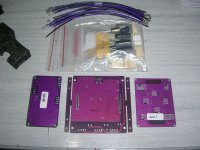
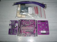
Mine arrived today.. Yay.! FedEx seemed to want to keep hold of it for another couple days for some reason. Better over zealous security than none I'd say.!
First thing when I opened I though oh hell. .they be some small SMD things and many of them!

Luckily not for us to populate ! I'd missed the updated post #1 with the soldering guide.
Look forward getting it in the system
Thanks Richard and wifey
First thing when I opened I though oh hell. .they be some small SMD things and many of them!
Luckily not for us to populate ! I'd missed the updated post #1 with the soldering guide.
Look forward getting it in the system
Thanks Richard and wifey
Hi all,
Just a quick update, I swapped out the Nich. BP's for FC and not surprisingly didn't notice any difference except that the FC's fit in the layout and look better.
I'm expecting my filter board today, and it should be pretty quick and simple to solder up, so that's next on deck.
G
Just a quick update, I swapped out the Nich. BP's for FC and not surprisingly didn't notice any difference except that the FC's fit in the layout and look better.
I'm expecting my filter board today, and it should be pretty quick and simple to solder up, so that's next on deck.
G
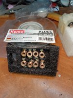
I finished the filter board (the difficult part).
George
George
Attachments
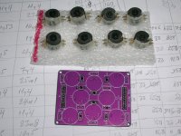
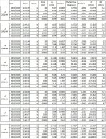
George - I admire your determination and perseverance to characterize the coils you've made, producing a spreadsheet of all relevant parameters must have taken a very long time! I note the ESRs you got are about 50% higher than mine (for the first three, higher still for the 4th) which implies you used thinner wire. 0.1mm for all ? I shall be interested to see how that choice impacts the frequency response of the final filter.
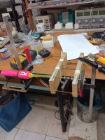
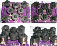
By the way wifey said if my glueing of the cores looked even half as messy as yours, I'd be dead meat! We apply the adhesive around the gap between the two halves, hoping it will sink into the crevice.
By the way wifey said if my glueing of the cores looked even half as messy as yours, I'd be dead meat! We apply the adhesive around the gap between the two halves, hoping it will sink into the crevice.
George,
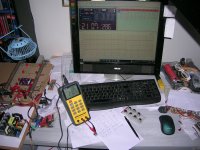
Really fantastic that you did this all yourself, and your test bench is very interesting. We are all interested in your impressions of how it sounds as well.
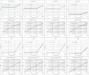
This last weekend I did some REW measurement of my setup with REW for THD, noise and FR. All of which looked very good, and as you all know I believe it sounds good too.
If interested I can post them up here, but I use a special laptop for this testing and all the data is at home on that computer.
G
Really fantastic that you did this all yourself, and your test bench is very interesting. We are all interested in your impressions of how it sounds as well.
This last weekend I did some REW measurement of my setup with REW for THD, noise and FR. All of which looked very good, and as you all know I believe it sounds good too.
If interested I can post them up here, but I use a special laptop for this testing and all the data is at home on that computer.
G
Hi Abrax
You know how the saying about measurements goes...
Yes. Unfortunatelly I couldn't source a 0.11mm or o.12mm wire. Only 0.1mm. And yes, the ESR goes up with the square of the diameter. (I wound a bobbin with 0.07mm wire and ESR went at 60 Ohm@1kHz).
With 0.1mm wire on all coils, Rs is 91 Ohm@1kHz from input to output of filter board.
My soundcard has developed some problems at it's output. Impedance tests at high Z are questionable. I have to open the hood and poke into it. Most probably I have to get another one.
Wifey eeh? Active women are experts into keeping their partner on his toes.
Besides pouring glue internally through the two sides openings, I apply the glue also at the bottom and the top externally, thus the mess.
George
- Home
- Vendor's Bazaar
- Dark LED passive filter-I/V stage for NOS DACs