Hi tube gurus,
Have you guys come across any current output tube amplifier / preamplifier?
I'm eager to test out tube based current output amplifier but I couldn't get any reference online except some preliminary discussions at tubecad.com. I do not see any real projects being made yet.
If you guys know of any, please do share the links or design here.")
Thanks a lot!
Ken
Have you guys come across any current output tube amplifier / preamplifier?
I'm eager to test out tube based current output amplifier but I couldn't get any reference online except some preliminary discussions at tubecad.com. I do not see any real projects being made yet.
If you guys know of any, please do share the links or design here.
Thanks a lot!
Ken
Hi tube gurus,
Have you guys come across any current output tube amplifier / preamplifier?
I'm eager to test out tube based current output amplifier but I couldn't get any reference online except some preliminary discussions at tubecad.com. I do not see any real projects being made yet.
If you guys know of any, please do share the links or design here.
Thanks a lot!
Ken
Sito Ultrasound Main Frame
Go to amplifiers. The Otello model (will cost you a fortune!
) uses vacuum tubes achieving 200Kohm Zout. The other models are Hybrid with SS output device. Just for the chronicles, these amps have been around for about 20 years now. I want to highlight this because I have read that some people recently have claimed new ideas, projects and patents....!!Yeah, I have seen they run something but doesn't seem to be bad.
For DIY one way could be an hybrid cascode output stage mosfet-pentode. To reduce the total gain one could use an input phase-splitting transformer with 2:1 (or 4:1, depending on the actual gain) step-down ratio. No voltage amplifier stage would be required I guess! Regulating the G2 voltage should reduce THD a lot. Shouldn't need feedback. The input transformer allows to run the amp in class AB otherwise, being a spud amp, a CCS would be ideal for balance but that would only allow class A operation.
Tubes like EL84 or 6CL6 look like a good candidates.
Last edited:
Any pentode output amp with no feedback will be a reasonable approximation to a current output amp. You need speakers to match, with much more mechanical resonance damping than is usual. That is why pentodes with no feedback are rarely used except in old radio sets.
Hi DF96,
Thanks for the reply! Making current source amplifier turns out to be simpler than I anticipated!
Can "more mechanical resonance damping" means stiffer cones/surrouds or lower Qts for the speakers? Yeah, I have seen they run something but doesn't seem to be bad.
For DIY one way could be an hybrid cascode output stage mosfet-pentode. To reduce the total gain one could use an input phase-splitting transformer with 2:1 (or 4:1, depending on the actual gain) step-down ratio. No voltage amplifier stage would be required I guess! Regulating the G2 voltage should reduce THD a lot. Shouldn't need feedback. The input transformer allows to run the amp in class AB otherwise, being a spud amp, a CCS would be ideal for balance but that would only allow class A operation.
Tubes like EL84 or 6CL6 look like a good candidates.
Hi 45,
Thanks 45! This term "hybrid cascode output stage mosfet-pentode" sounds a bit complicated - can you pls elaborate a little or show a sample schematic? A CCS load for a pentode is not difficult to build.
Ken
This term "hybrid cascode output stage mosfet-pentode" sounds a bit complicated - can you pls elaborate a little or show a sample schematic? A CCS load for a pentode is not difficult to build.
Ken
The CCS would be a current sink for the differential stage not a plate load. The output transformer is your load. The CCS would only allow class A operation and you have to use big valves for 10-15W. Instead if you use a phase-splitting transformer (which can be easier to make being step-down) you don't need the sink and can run the stage into AB and get some useful power from small pentodes as well.
About the hybrid cascode, instead of having a simple pentode differential stage you add a mosfet at the bottom of each tube. The signal enters the mosfet gate and then its drain is connected to the pentode cathode. You only need to bias the pentode properly using a resistive network.
To have high internal resistance from the pentodes use a separate supply for the G2 a lot lower than the plate voltage. For example the 6CL6 with 250V plate voltage and 150V G2 voltage has a plate resistance of 150K.
I have done some search on the internet and found this:
Softone Model7 technical description
In this case the pentode is triode-connected and feeback is used for bringing down the Zout to 4 ohm (damping factor = 2).
For a current amp this is not nedeed. Acutally, reading the tubecad journal, one could just use pentodes with high plate resistance like the 6CL6 above and then use feedback from the cathodes rather than the OPT to increase the Zout further.
Hi 45,
Thanks for the response and the interesting link.
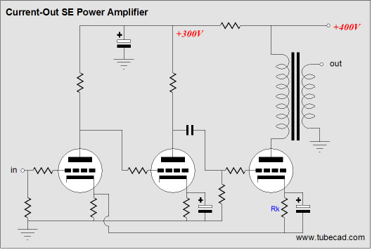
I also Googled and I found this circuit:
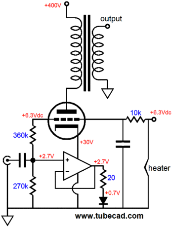
With pentode being a higher Rp tube, would it be a better choice instead of having the triode in the circuit?
Also, what's your thought of using tube instead of mosfet on the bottom (apart from the higher B+). Maybe I can do so below? Pentode cascode with OPT on top?
B+
|
OPT
|
pentode
|
pentode
|
ground
Br,
Ken
Thanks for the response and the interesting link.
I also Googled and I found this circuit:
With pentode being a higher Rp tube, would it be a better choice instead of having the triode in the circuit?
Also, what's your thought of using tube instead of mosfet on the bottom (apart from the higher B+). Maybe I can do so below? Pentode cascode with OPT on top?
B+
|
OPT
|
pentode
|
pentode
|
ground
Br,
Ken
Yes, pentode should achieve higher Zout than triode. The other advantage of pentodes is their efficiency. And yes, two pentodes will work.
If you don't want to use solid state you could also use a triode as lower device (or use the same pentode in triode mode) and make a triode-pentode cascode which would be easier to set up as you need to supply G2 just for one. Just check the capacintaces before choosing among equivalent solutions. The lower the caps the better.
If you don't want to use solid state you could also use a triode as lower device (or use the same pentode in triode mode) and make a triode-pentode cascode which would be easier to set up as you need to supply G2 just for one. Just check the capacintaces before choosing among equivalent solutions. The lower the caps the better.
P.S.
As I told before don't rule out a simple pentode output stage with feedback taken at the cathode resistor rather than the OT secondary.
Hi 45,
I've seen this mentioned in Tubecad on a 3 stage amplifier. Can this be done with a 2 stage amplifier?
Interesting thread!
Something I've been asking myself for a while: a pentode without feedback will have more uneven harmonics distortion, so what about using a triode with a large unbypassed cathode resistor (possibly even lifting grid to a positive voltage to allow even higher value for the cathode resistor)? Will this maintain the mostly even harmonics distortion usual from triodes?
many thanks, Erik
Are triodes mainly even? They are, like most active devices, mostly 2nd but 3rd and 4th appear too. Cathode degeneration will create some re-entrant distortion, while reducing the total disortion. Depending on the triode and bias point chosen, re-entrant 3rd may add or subtract from the intrinsic 3rd. If there is cancellation, then this is most likely with small cathode resistors (less than 1/gm) so probably smaller than might be used if you are trying to deliberately raise output impedance.ErikdeBest said:Will this maintain the mostly even harmonics distortion usual from triodes?
As a general rule, if you take the output from an 'evens-only' device and feed some back then you get odds too. If you do the same for an 'odd-only' device then you don't get evens produced. This is because of symmetry.
hi DF96
thanks for the answer. Apparently not easy to determine beforehand how cathode degeneration will influence distortion. Maybe the best testbed would be to have a CCS parallel with a variable resistor in the cathode? CCS determines most of the current, and the variable resistor determines the resistance in the cathode circuit?
Erik
- Status
- This old topic is closed. If you want to reopen this topic, contact a moderator using the "Report Post" button.
- Home
- Amplifiers
- Tubes / Valves
- current output tube amplifier