Hi everyone,
Does anyone have any knowledge or experience of building a Current-Dumping amplifier. I think Quad used this type of topology in the 909 and I would like to have a go at one of these amps.
If anyone knows of or can share some design info then I would appreciate any help.
Thanks
Gareth
Does anyone have any knowledge or experience of building a Current-Dumping amplifier. I think Quad used this type of topology in the 909 and I would like to have a go at one of these amps.
If anyone knows of or can share some design info then I would appreciate any help.
Thanks
Gareth
gareth said:Does anyone have any knowledge or experience of building a Current-Dumping amplifier. I think Quad used this type of topology in the 909 and I would like to have a go at one of these amps.
If anyone knows of or can share some design info then I would appreciate any help.
Hi Gareth,
I have not built one, but this site has lots of information about it, including Peter Walker's original article in Wireless World.
The 405 circuit works well too. You can get a circuit board for it on eBay that will help with construction. I have built several variations on the 405 without that circuit board and have been very pleased with the results. Not having to worry about setting the output bias current or having to try to track it is a big plus too.
I really feel the poor limiting circuit on the original gave it a bad name and that current dumping is vastly underrated.
Good luck!
I really feel the poor limiting circuit on the original gave it a bad name and that current dumping is vastly underrated.
Good luck!
I have obtained from China (Ebay) a set of the 405 boards and built myself a mini 405 . By recalculating a few values and using 2n3055 outputs and TIp 32a drivers switching the lm 311 for TL071 built a nice sounding amp of abouts 30 watts rms per channel more than enough for my Lowther spks
I can reccomend the boards highly they are not perfect but pretty close
delivery was within 2 weeks all in all a great buy
regards Trev
I can reccomend the boards highly they are not perfect but pretty close
delivery was within 2 weeks all in all a great buy
regards Trev
latala said:I have obtained from China (Ebay) a set of the 405 boards and built myself a mini 405 . By recalculating a few values and using 2n3055 outputs and TIp 32a drivers switching the lm 311 for TL071 built a nice sounding amp of abouts 30 watts rms per channel more than enough for my Lowther spks
I can reccomend the boards highly they are not perfect but pretty close
delivery was within 2 weeks all in all a great buy
regards Trev
Hi,
How much did the boards cost?
Thanks
Gareth
latala said:£10 a pair + postage
I seem to remember the seller was (tubehunter)
regards Trev
Hi,
Cheers Trev, thats a good price. Have you built the amps yet ? What do you think of them ?
Thanks
Gareth
The modules are built and have been listened to I am yet to put them in an enclosure !
What do I think? its a nice clean amp not world shattering but good!!!
I must add I used to be a quad dealer in the 70,s/80/s and always admired quad for the build quality but not much else
I only built them because I could .
I prefere the sound of my hitachie mosfet hma7500/phase linear 400b Sugden A41 amps but I have so many and I love them all
regards Trev
Hi,
i follow a circuit sheme, which may be a sort of current dumper. In my idea, a high-voltage small-power amplifier drives a resistor in series with the load, providing small signals to the load. In parallel to the resistor are emitter-basis diodes of a complementary bipolar transistor pair, which provides large signals.
This principle has been realized often, usually as overdrawn examples with a DIP-8 operational amplifier, which can provide only a few milliampères. Its output is mostly lost in the resistor and basis-emitter diodes, hence open- and closed-loop gains must be re-designed. But my idea is to use a power chip, which keeps controlling the load for most parts.
The practical challenge is to be able to put 50W into 4 Ohms, at 42V Vcc, not needing to use an oscilloscope for stability tests, using TDA2050. Vanilla, there were no safety power margin. I would like to take a load off its feet.
The load is to be decoupled from the amplifier at high frequencies using a choke, a cap and two resistors, as usually found in good amps. The resistor is to have 0.375 Ohms, so when the chip-amp outputs 1.5 A, one partner of the TO-220 transistor pair starts to conduct. The resistor is to consist of four metal-film 1.5 Ohms / 0.6W in parallel in order to have no inductance to speak of.
Large-signal bandwidth of TDA2050 with standard gain is 80 KHz. A lowpass of 40KHz (or even lower, as tweeter is gonna have its own vanilla TDA2050) should minimize chances of heat-up due to high-frequency noise. I do not see, why this would not work. Should i buy some parts and try?
Uli
Last edited:
This sounds interesting for both practical use and learning about "current dumping" operation. How about a circuit diagram, sketch etc. showing at least the fundamentals with your prescribed components in place? I'm fairly sure of what you mean generally but the details will be much easier to be sure of with a visual aid.
Perhaps a new thread about this new direction?
Perhaps a new thread about this new direction?
Hi everyone,
Does anyone have any knowledge or experience of building a Current-Dumping amplifier. I think Quad used this type of topology in the 909 and I would like to have a go at one of these amps.
If anyone knows of or can share some design info then I would appreciate any help.
Thanks
Gareth
Go to BX100
http://www.diyaudio.com/forums/solid-state/243345-current-dumping-amplifier-9.html
Apexaudio, the original current dumper and your thoughts about it are too complicated for me. My analogy: I mean to dump current of a quasi-class-A amplifier into a network consisting of resistor, basis-emitter diodes and load. One could also say flood instead of dump, make sure, the water gets into all crevices and wets everything. Now have valves regulating water height inside the container. Finally, have a hole at the bottom, where one draws water from.
Cambe, that is closer, but still too complicated.
Dear Ian, here is my sketch:
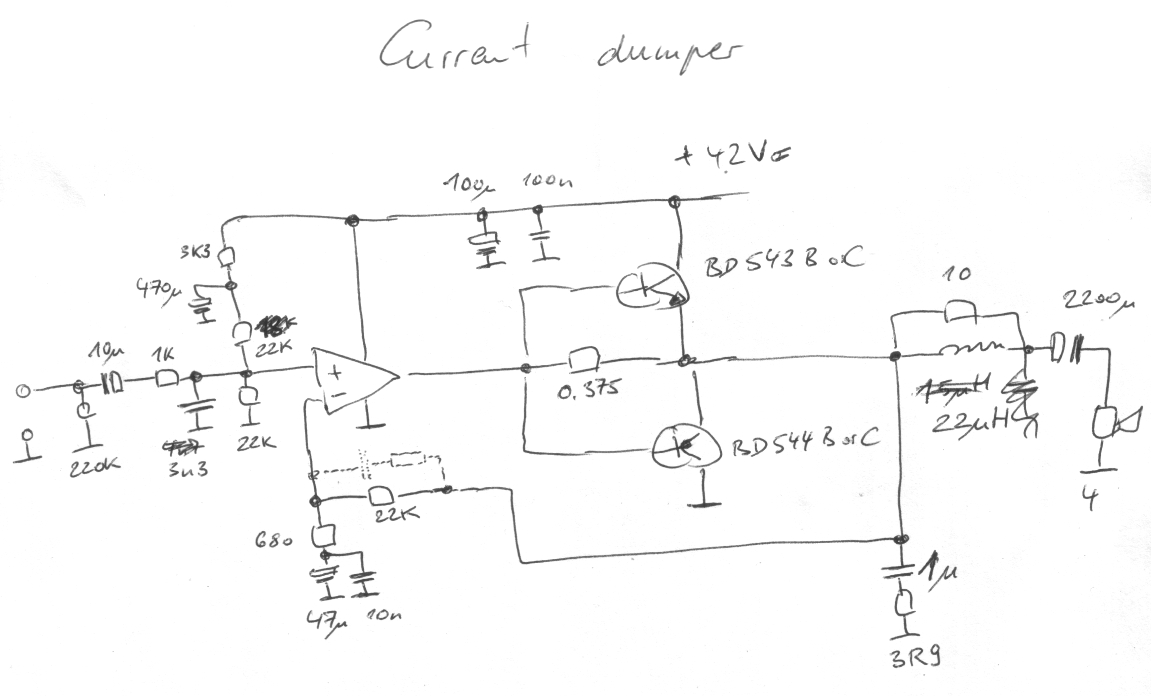
For the transistors, A types would also withstand voltages. The network consisting of HF blocking caps, TDA2050, 0.375 Ohms and feedback would need to sit within less than a square inch, so serial inductances are kept low.
Cambe, that is closer, but still too complicated.
Dear Ian, here is my sketch:
For the transistors, A types would also withstand voltages. The network consisting of HF blocking caps, TDA2050, 0.375 Ohms and feedback would need to sit within less than a square inch, so serial inductances are kept low.
Attachments
The 405 circuit works well too. You can get a circuit board for it on eBay that will help with construction. I have built several variations on the 405 without that circuit board and have been very pleased with the results. Not having to worry about setting the output bias current or having to try to track it is a big plus too.
I really feel the poor limiting circuit on the original gave it a bad name and that current dumping is vastly underrated.
Good luck!
Be aware that sometimes boards are offered as replacement for the 405 current dumping amp that are NOT CD amps but regular class (A)B amps! Beware!
Jan
Hi Guys
Grasso789's scheme when scaled up is essentially like the Crown DC-300, or Rod Elliot's 500W sub amp. The output stage is biased off and only turns on once a predetermined load current is being delivered by the amp or part of the amp that is always biased on. This can save significant dissipation but THD is not usually very good.
Taking that approach to a more hifi end, the output devices would be biased on a little bit, but the drivers would be biased hotter and would drive the load up to a point before the output devices really "kick in". With this approach, you can effectively have an EF4 that is very stable but exhibits single-ppm THD at 100s and even k's pf watts.
The original Quad circuit is described as a small class-A amp that drives the load to a low level but then class-B devices drive the load to high levels when needed. The combining of the outputs of the small amp and the current dumpers is via low-value Rs and chokes. After Walker's article in Wireless World, others from Sandman etc showed variations on this theme.
Have fun
If resistor swallows one tenth of amplitude, then open loop distortion due to current-dumping is around one tenth. This seems reasonable for an amplifier with 40 dB feedback at 1 KHz.
Open-loop distortion and chip current draw are easily measured, so i can evaluate different resistor values. For tab of TDA2050 is connected to minus of supply, and i plan single supply voltage, i will mount it without insolation, helping cooling.
Open-loop distortion and chip current draw are easily measured, so i can evaluate different resistor values. For tab of TDA2050 is connected to minus of supply, and i plan single supply voltage, i will mount it without insolation, helping cooling.
I would be glad, if someone could help me to simulate this in LTspice IV. I use "opamp2" component, which seems to be unable to output enuf current, no matter how hi i set "ilimit". Have a look at the attached spice file. I would be also glad, if someone could explain "Vos" and "rail" parameters to me.
Attachments
Never mind, i just scaled it down. Using 42dB feedback.
Helpers transistors start to conduct at high power, here relative currents of opamp (green) and transistors (red) at 15W output:
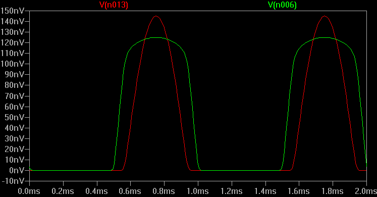
At this level, each harmonic is below -80dB, but their levels are not falling with harmonic number. This should be still o.k. for my purpose. Glitch is a new harmonic series starting at 128 KHz.
In typical use, chipamp will still draw most power. But it will never deliver high currents. Hence reliability should be much improved.
Helpers transistors start to conduct at high power, here relative currents of opamp (green) and transistors (red) at 15W output:
At this level, each harmonic is below -80dB, but their levels are not falling with harmonic number. This should be still o.k. for my purpose. Glitch is a new harmonic series starting at 128 KHz.
In typical use, chipamp will still draw most power. But it will never deliver high currents. Hence reliability should be much improved.
Attachments
Last edited:
- Status
- This old topic is closed. If you want to reopen this topic, contact a moderator using the "Report Post" button.
- Home
- Amplifiers
- Solid State
- Current-Dumper