I'm considering trying some KT120s in various bass guitar amps originally built for "lesser" tubes. I can add soft-start current-inrush limiting when standby mode is turned on for the sake of the power transformer, and plenty of capacitor energy storage to help average the demand more like a hi-fi amp. Which means the weak link may be the output transformer, which is also the most expensive part, and the whole point is to push it to its max (but hopefully not far beyond). Come on, we're all tinkerers, what can I do to improve its chances of survival? I can't just specify a heftier one.
I imagine that transformer failures are usually due to some spike in supply or load, insulation breakdown, etc., and a few degrees change in overall average operating temp might be irrelevant to what's happening momentarily deep within the hottest most vulnerable part of the windings. Yet running them cool probably does prolong life and improve performance. Look at how the power company uses liquid oil coolant and various radiators and tubes to improve performance and reduce cost. But I'm unknoledgeable about exactly what happens in the iron when it's saturated or carrying heavy eddy currents, but I imagine the heat generated in a transformer is not lnear with load wattage when it approaches its limit. Can I push that milit at all, with protective measures?
Of course a fan comes to mind, but what more can I do, and is there any value in the pursuit?
I have some deep-finned aluminum heat-sink. I have some heat-conductive electrically-insulating "loaded" potting epoxy. Is there any value to trying to cool a conventional E-core power or output transformer better? Cooling the bell-end covers probably isn't going to help very much, but even that can't hurt; I'm kind of surprised they're not finned. Can't really cool the copper windings directly very well. If I glue some heat-sink onto the iron core, it's going to be very difficult (to say the least) to disassemble in the future, not that that's likely anyway.
I could easily weld steel fins onto the bell-ends or glue on aluminum heat-sink, fill the bell-ends with potting epoxy, and bolt them on...forever. I could remove the bell-ends and put the entire transformer in a finned aluminum box or can filled with potting epoxy, like some Harmon-Kardon, McIntosh, and military equipment. Their intent seems more to prevent transformer vibration, prevent wire movement and insulation cracking, improve insulation, prevent flash-over, etc. rather than improve cooling. Sometimes high voltage trasnformers are potted in rubber that seems a better insulator than condutor of heat (and electricity, which is likely the point).
It seems both obvious and a little nuts. Is it pointless, futile, or just expensive? Any creative ideas or advice for a born tinkerer who just can't leave anything alone?
I suspect you can't make much difference. Ensuring good thermal contact between the transformer and a cool metal chassis may help a little. If the chassis itself is hot, as can happen with valves, then it won't help. A fan may help, if you can put up with the noise, but really only at the margins.
Having some sinks already, I would put them on three of the four sides of the laminations. Cut the heatsinks to exactly match the dimension of each side, a generous amount of heatgrease....thick enough to get into the irregularities of the lams, a nice colored Zip-tie for the sides, gravity for the top, ....perhaps cut the ends at 45 degrees????? cept for the bottom of the sides which will contact, or nearly contact the chassis.
_______________________________________________________Rick.........
_______________________________________________________Rick.........
I did something similar to what Richard is describing. Different scenario, as this is the power transformer of my tube amp, but same principle. I stripped some 14 gauge solid core electrical wire and used it secure the heat sink to the back-side of the transformer. Used some CPU thermal compound I had in the parts bin. Twisted the copper wire with pliers for a nice, tight fit.
Oh, it works, by the way.") Transformer used to run at about 170 or so, now stable for hours at around 148-149 (still pretty hot, really).
Transformer used to run at about 170 or so, now stable for hours at around 148-149 (still pretty hot, really).
As you can see, I had to modify the cage to accommodate the heat-sink, but nobody sees any of it unless I specifically show them.
Oh, it works, by the way.
Transformer used to run at about 170 or so, now stable for hours at around 148-149 (still pretty hot, really).As you can see, I had to modify the cage to accommodate the heat-sink, but nobody sees any of it unless I specifically show them.
An externally hosted image should be here but it was not working when we last tested it.
Last edited:
If you wanted to go "hardcore" with the idea above, you could get something like this...
...and strap a quiet-running 120cm fan to it. Rig up a 12v DC supply and Bob's yer uncle.
An externally hosted image should be here but it was not working when we last tested it.
...and strap a quiet-running 120cm fan to it. Rig up a 12v DC supply and Bob's yer uncle.
Like this, if you wanted to go with one straight out the back of the amp, like I did...
I have considered adding a fan and possibly going with a big heat-pipe. It gets very hot here in the summer and the amp is right by a huge window.
An externally hosted image should be here but it was not working when we last tested it.
I have considered adding a fan and possibly going with a big heat-pipe. It gets very hot here in the summer and the amp is right by a huge window.
Some random thoughts:
Do you know the secondary ht winding current spec? Are you wanting to run the idle at or near a level which is effectively the 'max rating' of the HT supply?
You may find that HT voltage regulation with increasing continuous sine output will mean a leveling off of output power capability, rather than any form of output valve overdrive limitation of rms output power.
The thermal lag of a few hundred watt transformer is going to be many tens of minutes - that is the outer measureable temperature of the core at steady state with a constant load on the transformer. The risk is that the winding temperature at the 'heart' of the core/winding will ramp up to exceed insulation limits in a time frame that is quicker than the capability to move the heat from the outer core surface.
Using a high C filtered diode rectifier forces high crest factor current waveform through te windings, making them less effective at transferring max power than if say you used a choke input filter.
Your heater winding is capable of a change in tube?
Unless your core is in a postion to allow airflow over an added heatsink to get in and escape, then the benefit of a heatsink can be quite restricted. Is the increase in power dissipation of transformer and valves going to cause a headache for the existing cooling scheme used in the amp, or is the transformer an independant part (with respect to cooling)?

TROBBINS - My first concern was the output transformer, but also the power transformer to a lesser degree. I haven't even decided which amp will be the guinea-pig yet; I suspect the SVT will have the biggest transformers. OOps, I mintioned guitar amps at risk of being shuffled off the the intrument forum. But I was thinking I'd get an aftermarket filament transformer for the preamp heaters, then the stock one should handle the KT120 heaters fine. Still lots to consider in issues of bias and driving 6 of them. Heck, I don't have coherent objectives and a balanced/proportional design yet. I'm still all googly-eyed over big tubes...
Fins and cooling tubes won't help you, because of poor contact with lamination and inexistent contact with copper windings.
I cool my transformers (have done it forever) with a fan, which blows air into them 1 inch or less away.
All of it, including windings, gets a cool air bath before anything else in the amp.
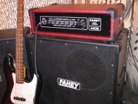
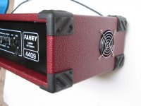
Here's my 300W bass amplifier, the EI transformer is straight in front of the fan:
After that, it goes on to cool the power MosFets and everything else.
Works like a charm, speacially because I do not lose power after 1 or many hours full blast; otherwise hot copper causes higher power losses.
I cool my transformers (have done it forever) with a fan, which blows air into them 1 inch or less away.
All of it, including windings, gets a cool air bath before anything else in the amp.
Here's my 300W bass amplifier, the EI transformer is straight in front of the fan:
After that, it goes on to cool the power MosFets and everything else.
Works like a charm, speacially because I do not lose power after 1 or many hours full blast; otherwise hot copper causes higher power losses.
Attachments
Hi happycamper - I guess any insight in to heat overloading an OT is a little bit more haphazard, as the original design may be aligned to other factors than what a normal PT would be designed on. It could well be that the OT would sound very distorted well before any overheating conditions kick in.
One comment is that if the speaker windings have taps, then try to use the highest % of turns available as possible (ie. if you have an 8 and 16 ohm output, then use a 16 ohm speaker - unless the tappings are very fancy and allow you to use all turns for 8 ohm).
Another comment is to perhaps try and integrate a high order subsonic filter aligned to your speaker systems useable bottom end - so as to minimise power used in a frequency range that has no benefit (and may degrade audio performance via saturating the OT).
If you ever move away from the land of eternal sun, you may want to address spikes in the AC supply. We get significant lightning strikes here. Actually, if you have an air conditioner, refrigerator or other motor, you may have up to 1100 Vdc spikes on your AC line. Do your insulation a favor and put an MOS spike suppressor on the input AC after the fuse. I like the 15 mm diameter ones, rated 300 VAC or so in the US. The 7 mm ones are used in low cost PCAT supplies, the 15 mm extra thick ones are used in $700 up VFD motor drives. The more mass, the more energy (joules) they will absorb. The distributors don't stock the extra thick ones. I don't want a 150 vac one, MOS supressors have a limited life and I don't want it doing its job every ******* vacuum cleaner shutoff. You can put one between hot and neutral, and between neutral and ground, in case your wall outlet is upside down. My old amps have ungrounded cases, so I use the hot to neutral one. Makes a nice tree grounding system with the master ground the turntable ground point on the preamp/mixer.I imagine that transformer failures are usually due to some spike in supply or load, insulation breakdown, etc., and a few degrees change in overall average operating temp might be irrelevant to what's happening momentarily deep within the hottest most vulnerable part of the windings.
Oh, and I've done load studies on candidate surplus transformers for transistor service. Some of them had an internal thermostat, and it would go off long before the metal frame was hot in some cases.
Last edited:
I must say I'm rather amused by these cooling contraptions. It seems, however, that the fundamental limitations of the transformer are not being addressed, namely, the peak magnetic field the transformer can support.
The maximum magnetic field is dependent on the core area, core materials, and any air gaps in the transformer. These are all fixed for a given transformer. So a 20 W transformer will support 20 W maximum without saturating the core. You can add as many cooling fans to it as you want, it's still only going to support 20 W.
Another issue is the loss in the windings. If you exceed the rated current for the primary or secondary winding, the winding will overheat and the insulation will break down. Adding a cooling fan might help against this failure mode. Though, I doubt it'll do much as the inner-most windings will still be screaming hot.
As with all engineering solutions there's some margin in the design. Generally, more margin means a more expensive product and lower profits, and for some scrupulous companies, the margin seems to be negative (i.e. components are routinely operated beyond their specified limits). So you may have some wiggle room for higher power. Or you may not...
Just sayin'...
~Tom
Also remember this is a guitar (bass) amp. Some output transformer saturation is probably desirable here. The trick is to maintain the saturation condition without melting the output transformer.
I have a 1953 Gretsch amp with a pair of 6V6's and a tiny output transformer stuck to the side of the 12" speaker in it...I'm sure it lives most of its working life saturated...but it sure sounds sweet!
I have a 1953 Gretsch amp with a pair of 6V6's and a tiny output transformer stuck to the side of the 12" speaker in it...I'm sure it lives most of its working life saturated...but it sure sounds sweet!
The real original issue was how to get more power thru the output transformer when upgrading to KT120 output tubes, without replacing the existing output transformer.
Thanks for the reality check. Cooling the output transformer may allow me to operate approaching and exceeding its limits more of the time. So cooling might make it safer to upgrade to KT120's (or might not). I might be able to hit that transformer a little harder & longer. But any temp change cooling the copper and core isn't going to really improve performance or deliver significantly more of that KT120 power to the speakers, so it's mostly a reliability mod, not a great one but possibly of value.
The best option I can think of for getting more watts of power thru the same output transformer might be to increase B+ voltage, as the output transformer winding and core limits are principally current limits. I suspect the longer (taller) plates of the KT120 excel at handling current, but a big plate handles power & radiates power losses without overheating, and it should handle more voltage. If I have more B+ and use that load line, judicious choice of speaker impedance and transformer output tap might deliver good power.
I can get only a bit more B+ voltage and power from the power transformer via less heat losses (and cooler running) if I use inductors in the filter ladder. Barring some kind of voltage doubler I'd still need to replace the power transformer or add some kind of supplemental power transformer(s).
- Status
- This old topic is closed. If you want to reopen this topic, contact a moderator using the "Report Post" button.
- Home
- Amplifiers
- Tubes / Valves
- cooling traditional E-core iron transformers