I'm playing around with a cascode configuration using 2 of the three triodes in an 'AK10 compactron. Once I get it worked out the third will be used as a concertina to drive something PP (not sure yet what I want to put there).
To keep the distortion down the lower cathode is not bypassed which cuts the gain about 2/3 (~160X to ~60X). Don't really need a lot, but I was looking around for ways to get some gain back and found a few references to adding a shunt resistor from B+ to the plate of the lower tube. This worked really well. The gain went up ~25% (all on the lower tube) with absolutely no change in distortion at the top. If anything it got a little better. This is like something for nothing, more gain and no increase in distortion.
So why don't I see this more often in circuits? Does it only help for tubes that want a fair amount of current? 'AK10 is rated for nominal 10ma on the plate.
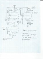
I can draw up a schematic if it's needed, but this is pretty much a generic cascode, except with a resistor from B+ to the point where the tubes connect plate to cathode.
To keep the distortion down the lower cathode is not bypassed which cuts the gain about 2/3 (~160X to ~60X). Don't really need a lot, but I was looking around for ways to get some gain back and found a few references to adding a shunt resistor from B+ to the plate of the lower tube. This worked really well. The gain went up ~25% (all on the lower tube) with absolutely no change in distortion at the top. If anything it got a little better. This is like something for nothing, more gain and no increase in distortion.
So why don't I see this more often in circuits? Does it only help for tubes that want a fair amount of current? 'AK10 is rated for nominal 10ma on the plate.
I can draw up a schematic if it's needed, but this is pretty much a generic cascode, except with a resistor from B+ to the point where the tubes connect plate to cathode.
All depends on the required voltages (say if you need the output plate at a lower voltage than ~2/3 B+) and if the devices are dissimilar or not (needing more current in one or the other).
You can get slightly more (RF) bandwidth by driving the top tube harder (i.e., using a larger input tube and running it at higher bias with a pull-up). In effect, you're getting a lower plate resistance, closer to the cathode-input resistance, which means more gain, and wasting less time swinging the top tube on and off. Obvious downside is more dissipation.
Nothing that matters for audio. (Of course, audio is easy; anything under about 100kHz is basically DC.)
Nice to see compactrons getting some love. They're sorely underappreciated. They had a tough job to do: compete with transistors! They were the highest performance tubes of the time, in the smallest/densest envelopes. You will regularly see high Gm and frame grid tubes for RF/IF and video, multiple triodes for chroma demux, and high current triodes and pentodes for deflection and amplification.
It's kind of too bad you can't DC couple to the splitter, but oh well. That said, you do have the option of a folded cascode -- downside is you need a relatively large coupling cap because of the low impedance. You'd end up burning a lot more current than simply coupling to the splitter, though.
Tim
If you increase the current in the lower valve then you increase its transconductance and, probably, move to a slightly more linear portion of the transconductance curve. For a cascode, voltage gain = lower transconductance x upper anode load (approximately).
You will also reduce the current in the upper valve but, within reason, this does less damage than the improvement in the lower valve so on balance you win.
You will also reduce the current in the upper valve but, within reason, this does less damage than the improvement in the lower valve so on balance you win.
So why don't I see this more often in circuits?
Audio Research has done this in a number of their preamps, the SP9 and SP11 for example (with fets in this case).
Last edited:
Shunt Resistor
Ale did this in his LCR preamp investigations. See: LCR Phono: design notes (Part III) | Bartola Valves
I also recall that GSI did a similar thing operating a 6DJ8 on the bottom with a double 12AX7 on top and a shunt resistor to boost the transconductance for their phono preamp.
Ale did this in his LCR preamp investigations. See: LCR Phono: design notes (Part III) | Bartola Valves
I also recall that GSI did a similar thing operating a 6DJ8 on the bottom with a double 12AX7 on top and a shunt resistor to boost the transconductance for their phono preamp.
Because it is very rare for someone to leave the bottom cathode unbypassed. Usually you want the full gain from the cascode, and you then lower the overall distortion with global feedback (or just put up with it). The alternative is to bypass only part of the cathode resistor, which has the advantage of not draining additional current from the HT.So why don't I see this more often in circuits?
A feed resistor like the one you're using is normally employed only when you need to squeeze every last drop of gain out of the cascode. Rarely do we need so much gain in our designs.
Last edited:
Thanks for all the info. This is as much an exercise in learning how the cascade works as anything else.
I did a series of tests this weekend with various values of shunt resistor and upper tube plate load resistor. With each change the tubes were both rebiased to -1V grid (more or less) to make comparisons apple-apple.
The biggest surprise to me is that changing the plate load on the top tube primarily alters the gain of the lower tube. Actually for a wide range of values the top tube's gain hardly changes at all, but the bottom one changes quite a bit. I'm having a hard time getting my head around this.
Last edited:
You need to be careful how you define 'gain' for a cascode. To a first approximation the lower valve provides transconductance gain, but no voltage gain, while the upper valve simply passes on the current from the lower valve into the load resistance.
How much signal voltage is developed at the lower anode/upper cathode is of little consequence, so trying to apportion voltage gain between the two valves is not usually helpful. One exception: if you are designing an RF cascode then you may be interested in this as it affects the Miller capacitance seen at the input.
How much signal voltage is developed at the lower anode/upper cathode is of little consequence, so trying to apportion voltage gain between the two valves is not usually helpful. One exception: if you are designing an RF cascode then you may be interested in this as it affects the Miller capacitance seen at the input.
Here is where it is at right now. It's working well enough to go ahead with part 2 of the project and have it drive a dual pentode to make a tiny 1W-ish push-pull amp. I characterized it at 6V PP output because I already know from previous testing this will drive the tubes I have in mind, probably a 'BN11 dual pentode.
So far the most expensive part of the project was the 2W output transformer that cost $25 from musicalpowersupplies.com. I bought 2 so maybe I can make a little headphone amp or something.
I plan on using up some of the gain with global NFB when it's all done, there's more than enough for what I need to do with it.
Attachments
Is the THD really *that* bad for such a small signal level?!
Yes it is, and I'm not sure why. It actually seems to get better with higher signal levels. The cascode by itself and the cathodyne by itself looked much better. I'm going to play around with it some more, one possibility it that it's just a result of my chaotic "protoboard" wiring.
Yes it is, and I'm not sure why. It actually seems to get better with higher signal levels. The cascode by itself and the cathodyne by itself looked much better. I'm going to play around with it some more, one possibility it that it's just a result of my chaotic "protoboard" wiring.
It was user error of a subtle kind: not understanding my instruments. I use a Picoscope 2206 8-bit digital scope with signal generator. It was set for THD%.
The problem is that the signal generator output at low levels contains quantization "stairsteps", which I'd noticed but ignored (shame on me, I've been a professional engineer for 35 years, I should know better than to ignore things that don't seem quite right...).
Maybe there is a way to fix this in the settings... RTFM. But for now I put a 10:1 attenuator on the signal generator and cranked it up to 10X the signal and the test sine wave is nice and smooth, and THD=0.15%. Is this more reasonable? I still don't know enough about these circuits to know what "good" is here, but this seems more in line with my earlier measurements, which used higher signal levels.
One other change that did make a small difference was to up the bypass cap on the upper tube in the cascode to 1uf from 0.1uf.
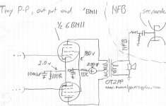
Took me awhile to get back to this. I've cobbled together an output section for this circuit (see attached), mainly just to see how it could work. A couple of questions have come up:
1. In the attached schematic in the upper right I've sketched out how I'm introducing NFB into the cascode. I didn't really think it through much, I just tried it and it seems to work pretty well. Any drawbacks to doing it this way?
2. Biasing the upper tube in the cascode with a voltage divider is a little tricky. I've tried three different tubes and all required re-biasing. Either I can put a pot in there or find a better way to bias. Any suggestions? I tried a battery from the cathode to the grid, which actually worked OK but seems kind of awkward.
Thanks....
Attachments
Could you say more about your problems with biasing the upper tube?
Sure. Referring back to the schematic I posed a few days back, the bias is set at 107V by a pair of resistors (390K, 270K), to be -1V relative to the 108V on the cathode.
When I tried different tubes from different manufacturers I had to change the divider to get the same -1 V bias. It only takes a few percent difference in the characteristics to put the bias off pretty far. Right now I just stuck a pot in the middle so I can adjust the bias to -1 V. But I don't like "fiddly" bits in a design if I can avoid them. I tried a lithium battery from the cathode, in series with a 1M resistor and a bypass cap from the positive end of the battery to ground. This makes for a steady bias V, but it's -1.8V, not optimal, and the battery becomes another fiddly bit to worry about.
Are there better ways to deal with this?
A triode valve has three linked characteristics: grid-cathode voltage, anode-cathode voltage and anode/cathode current. You can fix any two of these (or two combinations) and then you get the third determined by the valve.
If you want -1.8V bias then you have to set that, then depending on the circuit details the valve will balance off anode-cathode voltage against current. This may or may not give you the operating point you intend.
This is not the usual way to bias the upper valve in a cascode because most people don't care what the grid bias is, instead they want a particular current or a particular anode voltage. To get the former (roughly) you use a cathode resistor to bias the upper valve; then the anode voltage will settle to whatever is decided by the balance between the two valves. To get the latter you use a potential divider to bias the upper valve; then the current will settle to whatever is decided by the bias and characteristics of the lower valve.
- Status
- This old topic is closed. If you want to reopen this topic, contact a moderator using the "Report Post" button.
- Home
- Amplifiers
- Tubes / Valves
- Cascode question re shunt to lower tube